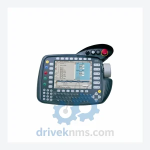
KUKA KCP2 VKCP2 Robot Control Panel – KCP Series
Commercial availability is handled through direct RFQ, model verification and export-oriented follow-up rather than public cart checkout.
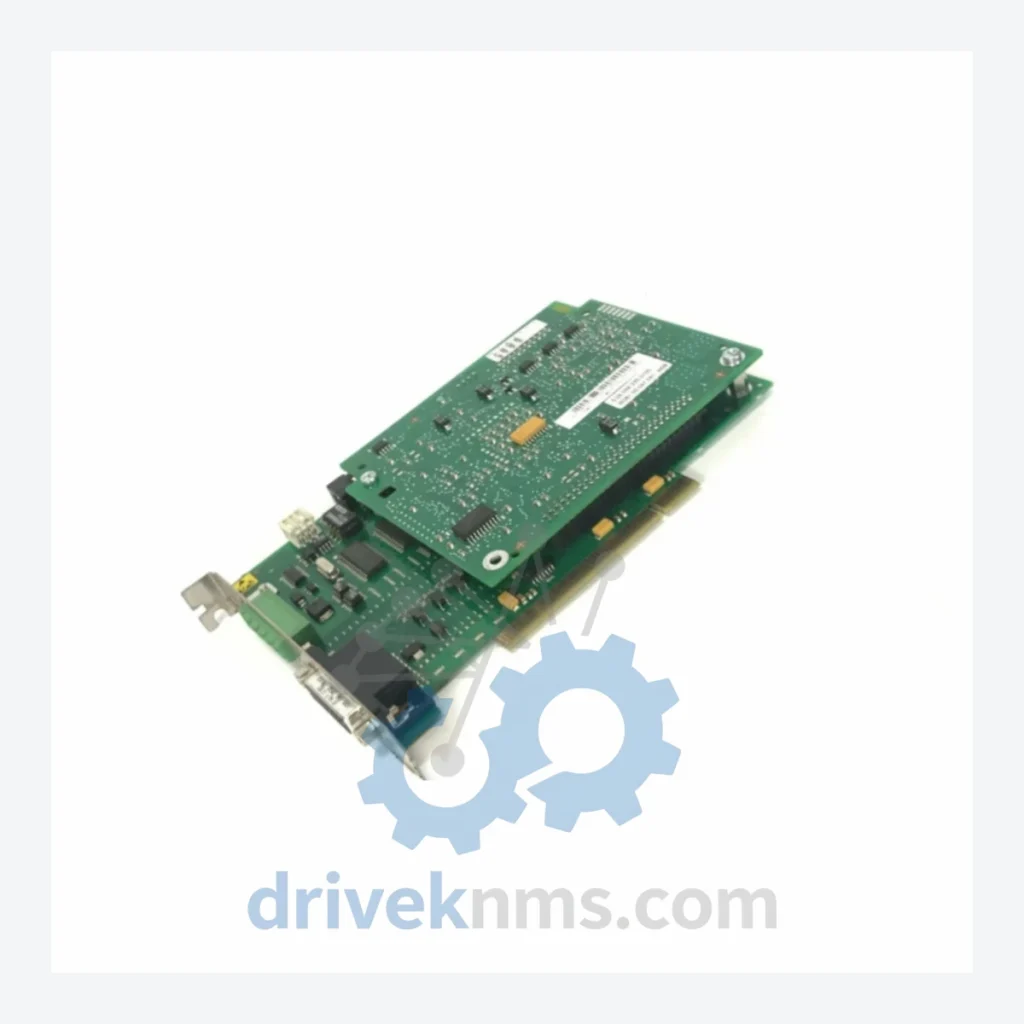
Model: MFC3 00-117-336
Product Overview
Commercial availability is handled through direct RFQ, model verification and export-oriented follow-up rather than public cart checkout.
Datasheet Preview
Use attached product manuals when available. If the manual is not public yet, request the full file directly through RFQ.
Commercial Path
Product pages on DRIVEKNMS are designed to verify model, brand and series first, then move the buyer into one clean quotation path.
Technical Dossier
The KUKA MFC3 (Multi-Function Computer 3) card, part number 00-117-336, is the central processing and communication board installed in KUKA KRC2 robot controllers. This card manages real-time motion interpolation, fieldbus communication, and I/O coordination across the entire robot cell. When this board fails, the robot controller is non-functional — there is no partial workaround.
| Attribute | Detail |
|---|---|
| Part Number | 00-117-336 |
| Model | MFC3 (Multi-Function Computer 3) |
| Compatible Controller | KUKA KRC2 (all variants) |
| Brand | KUKA Roboter GmbH |
| Country of Origin | Germany |
| Product Status | Discontinued / Obsolete |
| Form Factor | ISA/PCI hybrid backplane card |
| Operating System Compatibility | Windows XP Embedded (KRC2 platform) |
| Communication Interfaces | DeviceNet, Profibus-DP, Ethernet (via onboard ports) |
| Successor Platform | KUKA KRC4 (requires full controller replacement) |
The KUKA KRC2 controller platform was the dominant robot controller in automotive body-in-white, foundry, and general assembly applications from approximately 1996 through 2012. Tens of thousands of KRC2 units remain in active production service globally, particularly in facilities where the capital cost of full robot replacement cannot be justified within current budget cycles.
The MFC3 card is the single most failure-prone board in the KRC2 architecture. It is exposed to sustained thermal cycling, vibration, and in many installations, inadequate cabinet cooling. Failure modes include corrupted boot sequences, loss of fieldbus communication, and complete controller lockout. Because the MFC3 integrates motion control, I/O management, and network communication on a single board, there is no functional substitute within the KRC2 platform — the card must be replaced like-for-like.
KUKA ceased manufacturing MFC3 boards as part of the KRC2 end-of-life process. Official KUKA service channels no longer carry this part. Facilities that have not pre-positioned spare MFC3 inventory face the following decision when a failure occurs: source from the secondary market immediately, or commit to a full controller upgrade under emergency conditions — the worst possible procurement scenario for capital equipment.
DriveKNMS specializes in exactly this gap. We maintain sourced, tested, and documented MFC3 00-117-336 units for facilities that need to extend KRC2 asset life by 5 to 10 years without a platform migration.
All MFC3 00-117-336 units processed by DriveKNMS undergo a structured 5-step quality verification protocol before dispatch:
Related Paths
Commercial availability is handled through direct RFQ, model verification and export-oriented follow-up rather than public cart checkout.

Commercial availability is handled through direct RFQ, model verification and export-oriented follow-up rather than public cart checkout.
Commercial availability is handled through direct RFQ, model verification and export-oriented follow-up rather than public cart checkout.