Lam Research 810-099175-103 Assembly – Obsolete Spare Part
Lam Research 810-099175-103 Assembly – Obsolete Spare Part When a critical assembly on a Lam Research etch or CVD system…
Model: ADIO RS485, ROHS 810-227611-003 0200-01009 0090-08888
Product Overview
Commercial availability is handled through direct RFQ, model verification and export-oriented follow-up rather than public cart checkout.
Datasheet Preview
Use attached product manuals when available. If the manual is not public yet, request the full file directly through RFQ.
Commercial Path
Product pages on DRIVEKNMS are designed to verify model, brand and series first, then move the buyer into one clean quotation path.
Technical Dossier
The LAM RESEARCH ADIO RS485 series represents a class of Analog/Digital I/O interface boards deployed extensively across semiconductor fabrication equipment, chemical vapor deposition (CVD) systems, and etch process chambers. LAM Research Corporation, headquartered in Fremont, California, has supplied these subsystem boards as integral components of its Versys, Kiyo, Flex, and 2300 platform tool families. These boards are installed in facilities operating under ISO Class 1–5 cleanroom conditions, including fabs operated by TSMC, Samsung, Intel, and GlobalFoundries. The ADIO RS485 board specifically handles analog input/output signal conditioning and RS-485 serial communication interfacing between the tool's main controller and peripheral subsystems such as gas delivery, RF matching networks, and endpoint detection modules. Given the 10–20 year operational lifespan of semiconductor process equipment, demand for ADIO RS485 replacement boards remains active well beyond the original production window.
The ADIO RS485 board architecture evolved through several generations tied to LAM Research's platform transitions. Early-generation boards (circa 1995–2002) used discrete analog signal conditioning ICs with 12-bit ADC resolution and supported RS-485 half-duplex communication at 9600–115200 baud. These boards interfaced via proprietary backplane connectors to the tool's VME or cPCI-based main controller chassis.
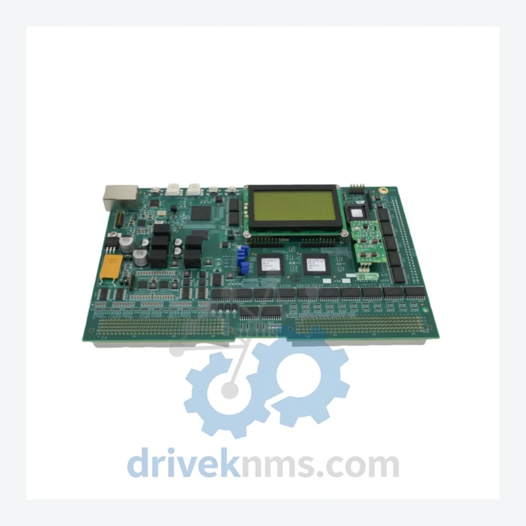
Mid-generation revisions (2003–2010) introduced RoHS-compliant component substitutions, reflected in the ROHS suffix designation on part numbers such as 810-227611-003. These revisions maintained backward electrical compatibility but required firmware updates on the host controller to recognize revised board identification registers. The LCD Display BD variant (as designated in the full part description) added a local diagnostic display interface, enabling field engineers to read analog channel values and RS-485 bus status without connecting a laptop.
Later revisions incorporated enhanced EMI filtering and conformal coating for use in corrosive process gas environments. Compatibility between board revisions is constrained by the backplane slot assignment and the firmware version of the host Lam controller; cross-revision substitution requires verification of the board's hardware revision register against the tool's BOM.
The following SKUs represent verified part numbers within the LAM RESEARCH ADIO RS485 and closely related ADIO board families used across Lam Research etch and CVD platforms. Each entry reflects a distinct hardware revision, RoHS compliance status, or functional variant.
810-227611-003: ADIO RS485 RoHS-compliant main board, LCD display variant, current production reference.
0200-01009: Sub-assembly reference for ADIO RS485 analog front-end daughterboard.
0090-08888: LCD display board sub-assembly, mounts to ADIO RS485 main board.
810-227611-001: ADIO RS485 first-release revision, non-RoHS, no LCD interface.
810-227611-002: ADIO RS485 intermediate revision, partial RoHS, no LCD.
810-227611-004: ADIO RS485 extended-temperature variant for high-ambient-temperature tool configurations.
0200-00876: Analog I/O conditioning board, 16-channel AI, used in Versys Metal platform.
0200-01102: Digital I/O expansion board, 32-channel DI/DO, RS-485 bus compatible.
0200-01245: ADIO RS485 replacement board for 2300 Flex etch platform, RoHS.
0090-07654: Backplane interface connector assembly for ADIO series boards.
0200-00654: Analog output board, 8-channel AO, 16-bit DAC, RS-485 interface.
810-056789-001: ADIO communication adapter board, RS-485 to Ethernet bridge module.
0200-01350: ADIO RS485 board for Kiyo etch chamber, conformal-coated variant.
0090-09001: Power regulation sub-board for ADIO RS485 series, ±15V and +5V rails.
810-227611-005: Latest known revision of ADIO RS485, RoHS, enhanced EMI filtering, LCD display.
The ADIO RS485 series has entered the mature-to-declining phase of its product lifecycle. LAM Research no longer lists these boards as orderable through standard OEM channels for tools outside active service contracts. For fabs operating legacy Versys, Kiyo, or 2300-series tools, this creates a critical spare parts gap: a single failed ADIO RS485 board can halt a process chamber indefinitely if no replacement is available.
DriveKNMS maintains a dedicated inventory of LAM RESEARCH ADIO RS485 boards sourced through certified secondary market channels. All units are inspected against original LAM Research engineering drawings where available. DriveKNMS provides cross-reference matching between obsolete part numbers and their functional equivalents, and can advise on firmware compatibility requirements for board substitution. For fabs requiring long-term maintenance agreements covering ADIO RS485 and related I/O subsystem boards, DriveKNMS offers consignment stocking arrangements and priority allocation for critical spares.
Contact DriveKNMS with your tool serial number, current board part number, and hardware revision to receive a compatibility-verified replacement quotation.
ADIO RS485 boards present specific test challenges due to their combined analog signal conditioning and RS-485 digital communication functions. DriveKNMS applies the following test protocol to all ADIO RS485 units prior to shipment:
Analog Channel Verification: Each analog input channel is stimulated with a calibrated voltage source across the full input range (typically 0–10V or ±10V). ADC output codes are verified against expected values at 0%, 25%, 50%, 75%, and 100% of full scale. Channel-to-channel crosstalk is measured and must remain below the original specification threshold.
Analog Output Verification: Each DAC output channel is loaded with a precision resistor and output voltage is measured at multiple code points. Linearity error must remain within ±1 LSB of the 16-bit specification.
RS-485 Bus Test: The board is connected to a test fixture replicating the tool's RS-485 bus topology. Communication integrity is verified at 9600, 57600, and 115200 baud. Bus termination impedance is checked. Half-duplex direction control timing is verified against the LAM Research protocol specification.
LCD Display Interface Test: For boards carrying the LCD Display BD designation, the display sub-assembly is powered and all character positions are exercised. Contrast and backlight function are verified.
Backplane Connector Inspection: All edge connector pins are inspected under magnification for oxidation, mechanical damage, and solder joint integrity. Pins are cleaned and re-tensioned where required.
Burn-In: Boards are operated at elevated ambient temperature (50°C) for a minimum of 4 hours under simulated load conditions to screen for early-life component failures.
Related Paths
Lam Research 810-099175-103 Assembly – Obsolete Spare Part When a critical assembly on a Lam Research etch or CVD system…
Lam Research VME-LTNI-S4 B105-0102 Network Interface Board: Supply Continuity Strategy for Semiconductor Fab Procurement Teams The Lam Research VME-LTNI-S4 B105-0102…
Lam Research 853-025054-008 Power Supply – Obsolete Semiconductor Spare Part When a power supply module fails inside a Lam Research…