GE UR Series Modules: UR6AV Digital I/O Module —
GE UR Series: Comprehensive Module Range and Technical Overview The GE Grid Solutions UR Series (Universal Relay) platform is one…
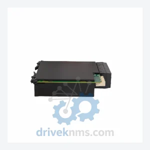
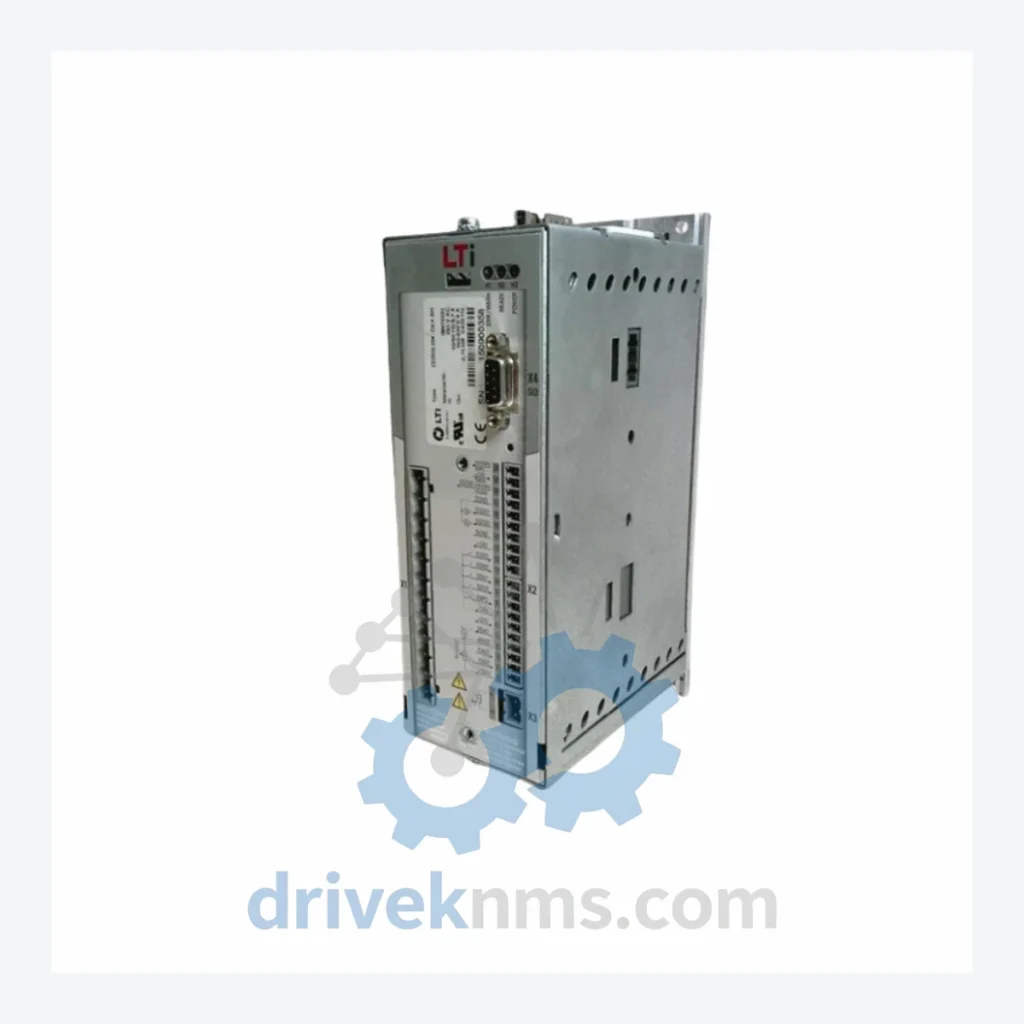
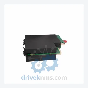
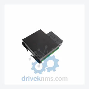
Model: CDB32.008.W2.2.BR CDB32.008.W2.2.BR.PC1
Product Overview
Commercial availability is handled through direct RFQ, model verification and export-oriented follow-up rather than public cart checkout.
Datasheet Preview
Use attached product manuals when available. If the manual is not public yet, request the full file directly through RFQ.
Commercial Path
Product pages on DRIVEKNMS are designed to verify model, brand and series first, then move the buyer into one clean quotation path.
Technical Dossier
The LUST CDB32 is a compact, single-axis servo drive platform engineered for precision motion control in demanding industrial environments. Manufactured in Germany by LUST Antriebstechnik GmbH (now integrated into the Rexnord / Nidec portfolio), the CDB32 series has accumulated significant installed base across chemical processing plants, refinery automation systems, nuclear facility auxiliary drives, and continuous-process manufacturing lines globally. Its 24 VDC logic supply architecture, CANopen and PROFIBUS-DP fieldbus options, and modular expansion slot design made it a preferred choice for OEMs building multi-axis coordinated motion systems throughout the late 1990s and 2000s. The series operates across a current range from 2.5 A to 34 A continuous output, covering a broad spectrum of servo motor frame sizes. The CDB32 platform is now in its end-of-life phase; however, installed base density in heavy industry ensures sustained demand for spare units, repair services, and functional replacements.
The CDB32 succeeded the earlier LUST CDB10 and CDB20 single-axis drive families, inheriting their 24 VDC auxiliary supply topology while introducing a 32-bit DSP control core that enabled significantly tighter current loop bandwidths (up to 5 kHz). The base unit accepts resolver or incremental encoder feedback natively; the .PC1 option card extends this to support SinCos high-resolution encoders and EnDat 2.1 absolute encoders, enabling sub-micron positioning resolution when paired with appropriate servo motors.
Fieldbus integration evolved across hardware revisions: early CDB32 units relied on RS-232/RS-485 point-to-point commissioning via the LUST DriveManager software tool. Subsequent revisions introduced the CANopen DS402 motion profile (CiA 402) via the .CAN option slot, and PROFIBUS-DP V1 via the .PB option card. The .BR suffix in the SKU CDB32.008.W2.2.BR denotes the integrated braking resistor circuit variant, eliminating the need for an external chopper module in applications with high regenerative energy (e.g., vertical axes, high-inertia loads). The W2 designation indicates the 200–240 VAC single-phase or three-phase input voltage class; the .2 suffix identifies the 8 A continuous / 16 A peak current rating within the W2 voltage class.
Compatibility note: CDB32 drives are not pin-compatible with the successor CDB34 or the current-generation LUST CDD3000 platform. Firmware is drive-specific and cannot be cross-flashed between hardware revisions. Replacement without re-engineering the control cabinet requires sourcing an identical CDB32 unit.
The following SKUs represent the documented CDB32 product range. Each entry reflects a distinct hardware configuration. Units marked with an asterisk (*) are confirmed end-of-life with no OEM new-stock availability.
CDB32.002.W2.2: 2.5 A cont. / 5 A peak, 230 VAC input, no braking resistor, resolver feedback standard *
CDB32.004.W2.2: 4 A cont. / 8 A peak, 230 VAC, standard I/O, resolver input *
CDB32.008.W2.2: 8 A cont. / 16 A peak, 230 VAC, standard configuration, resolver *
CDB32.008.W2.2.BR: 8 A cont. / 16 A peak, 230 VAC, integrated braking resistor circuit *
CDB32.008.W2.2.BR.PC1: 8 A / 16 A peak, 230 VAC, braking resistor + SinCos/EnDat encoder option card *
CDB32.012.W2.2: 12 A cont. / 24 A peak, 230 VAC, standard I/O *
CDB32.012.W2.2.BR: 12 A cont. / 24 A peak, 230 VAC, integrated braking resistor *
CDB32.016.W2.2: 16 A cont. / 32 A peak, 230 VAC, standard I/O *
CDB32.016.W2.2.BR: 16 A / 32 A peak, 230 VAC, braking resistor variant *
CDB32.008.W4.2: 8 A cont. / 16 A peak, 400–480 VAC three-phase input, standard *
CDB32.008.W4.2.BR: 8 A / 16 A peak, 400–480 VAC, integrated braking resistor *
CDB32.012.W4.2: 12 A cont. / 24 A peak, 400–480 VAC, standard I/O *
CDB32.016.W4.2: 16 A cont. / 32 A peak, 400–480 VAC, standard I/O *
CDB32.024.W4.2: 24 A cont. / 48 A peak, 400–480 VAC, high-current frame *
CDB32.034.W4.2: 34 A cont. / 68 A peak, 400–480 VAC, maximum current rating in series *
CDB32.008.W2.2.CAN: 8 A / 16 A peak, 230 VAC, CANopen DS402 fieldbus option *
CDB32.008.W2.2.PB: 8 A / 16 A peak, 230 VAC, PROFIBUS-DP V1 fieldbus option *
The CDB32 series reached official end-of-life status. OEM new-stock is no longer available through standard distribution channels. DriveKNMS maintains a dedicated inventory of tested, functional CDB32 units sourced from decommissioned plant equipment, controlled factory closures, and verified surplus channels. For critical production lines where a CDB32 failure would result in unplanned downtime, DriveKNMS provides: same-unit replacement with full functional verification, cross-reference advisory for CDB32-to-CDD3000 migration where re-engineering is feasible, and emergency dispatch for time-critical plant maintenance scenarios. All units are stored in ESD-safe, climate-controlled conditions to preserve IGBT and capacitor integrity.
Each CDB32 unit processed by DriveKNMS undergoes a structured multi-stage verification protocol. Stage 1: visual inspection of the power stage PCB for capacitor bulge, IGBT gate resistor degradation, and backplane connector pin integrity. Stage 2: auxiliary supply energization at 24 VDC with firmware boot verification and fault register readout via RS-232 using LUST DriveManager. Stage 3: full power-stage load test at rated current using a resistive load bank, verifying current loop response, overcurrent protection trip thresholds, and braking resistor activation (for .BR variants). Stage 4: encoder interface verification for .PC1 option cards, confirming SinCos signal amplitude and EnDat communication integrity. Test records are retained per unit serial number and available upon request.
© 2026 DriveKNMS. All trademarks belong to their respective owners. Specifications are for reference only and subject to change without notice. Verify all parameters against official documentation before installation.
Related Paths
GE UR Series: Comprehensive Module Range and Technical Overview The GE Grid Solutions UR Series (Universal Relay) platform is one…
GE Multilin UR Series: Comprehensive Module Range and Technical Overview The GE Multilin Universal Relay (UR) Series represents one of…
GE UR Series: Comprehensive Module Range and Technical Overview The GE UR (Universal Relay) Series, developed by GE Grid Solutions…