
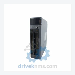
Mitsubishi QX48Y57 BD627B662G51 Combination Unit – PLC Module
Mitsubishi Electric QX48Y57 BD627B662G51 is listed for Servo Drives RFQ review. Confirm quantity, condition and destination before quotation.
RFQ-ready industrial model
Model: MR-H100ACN
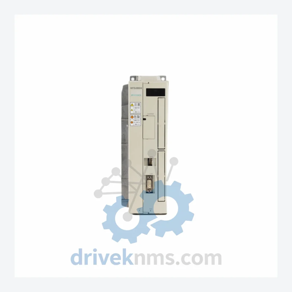
Product Overview
Commercial availability is handled through direct RFQ, model verification and export-oriented follow-up rather than public cart checkout.
Datasheet Preview
Use attached product manuals when available. If the manual is not public yet, request the full file directly through RFQ.
Commercial Path
Product pages on DRIVEKNMS are designed to verify model, brand and series first, then move the buyer into one clean quotation path.
Technical Dossier
The MR-H series was introduced as a successor to Mitsubishi's earlier MR-S and MR-SA analog servo families, incorporating a dedicated ASIC-based current control loop and a 17-bit incremental encoder interface. The drive communicates via analog ±10 V velocity/torque command inputs and supports pulse-train position commands, making it compatible with a broad range of CNC controllers and general-purpose PLCs of its era, including Mitsubishi's own MELSEC Q and A-series motion controllers.
The architecture uses a three-phase IGBT inverter bridge with integrated regenerative braking resistor terminals. Key compatibility constraints include: the MR-H series requires a dedicated HC/HA-series servo motor with matched encoder cable (MR-ENCBL series); it does not support the later MR-J2S or MR-J3 SSCNET fiber-optic bus protocol. Facilities migrating from MR-H to modern platforms must account for encoder signal conversion and parameter re-mapping when substituting MR-J4 or MR-J5 drives.
The series lifecycle is classified as mature/end-of-life. Mitsubishi Electric has discontinued active production of MR-H drives. The recommended modern migration path is the MR-J4 series (SSCNET III/H) or MR-J5 series (EtherCAT). For facilities unable to execute a full retrofit, DriveKNMS provides long-term maintenance inventory and tested replacement units to extend operational life.
The following SKUs represent verified models within the Mitsubishi MR-H series. Units are classified by output capacity and command interface type.
MR-H10ACN: 100W analog AC servo amplifier, ±10V velocity command, single-phase 200VAC input.
MR-H20ACN: 200W analog AC servo amplifier, pulse/analog dual command, single-phase 200VAC.
MR-H40ACN: 400W AC servo amplifier, three-phase 200VAC, built-in regenerative resistor.
MR-H60ACN: 600W AC servo amplifier, three-phase 200VAC, dynamic brake integrated.
MR-H100ACN: 1kW AC servo amplifier, three-phase 200VAC, analog/pulse command, 17-bit encoder support.
MR-H200ACN: 2kW AC servo amplifier, three-phase 200VAC, high-inertia load compensation.
MR-H350ACN: 3.5kW AC servo amplifier, three-phase 200VAC, extended regenerative capacity.
MR-H500ACN: 5kW AC servo amplifier, three-phase 200VAC, heavy-duty industrial frame.
MR-H700ACN: 7kW AC servo amplifier, three-phase 200VAC, large-frame IGBT module.
MR-H10ACN-S084: 100W special-spec variant, modified I/O connector layout for OEM integration.
MR-H40ACN-S084: 400W OEM-spec variant, customized parameter defaults.
MR-H100ACN-S084: 1kW OEM-spec variant, factory-preset gain tuning for specific motor pairing.
MR-H200ACN-S084: 2kW OEM-spec variant, modified regenerative threshold settings.
MR-H10AN: 100W earlier sub-variant, single-phase input, predecessor to ACN suffix models.
MR-H20AN: 200W earlier sub-variant, analog command only, no pulse-train input.
MR-H40AN: 400W earlier sub-variant, three-phase 200VAC, no built-in dynamic brake.
MR-H100AN: 1kW earlier sub-variant, analog velocity command, predecessor to MR-H100ACN.
MR-H200AN: 2kW earlier sub-variant, three-phase 200VAC, analog torque/velocity modes.
MR-H series drives incorporate a multi-layer PCB backplane with surface-mount power components and a dedicated encoder signal processing board. DriveKNMS applies the following test protocol to all MR-H units prior to dispatch:
1. Power-on self-test: Verify display initialization and absence of fault codes (AL.10–AL.99 range).
2. IGBT gate drive verification: Oscilloscope check of PWM switching waveforms at rated carrier frequency.
3. Encoder interface test: Signal integrity check on A/B/Z differential encoder lines using a reference encoder simulator.
4. Analog command response: Velocity loop response test at ±10V command input, confirming gain linearity.
5. Regenerative circuit check: Resistor continuity and IGBT regenerative path switching verification.
6. Thermal cycling: 30-minute load cycle at rated current to confirm thermal management integrity.
7. Parameter retention test: EEPROM read/write cycle to confirm parameter memory integrity after power cycle.
Continue The Model Path
Move from this exact model into the matching system hub, brand archive, model-family archive or lifecycle sourcing route before sending a final RFQ list.
Related Paths
Mitsubishi Electric QX48Y57 BD627B662G51 is listed for Servo Drives RFQ review. Confirm quantity, condition and destination before quotation.
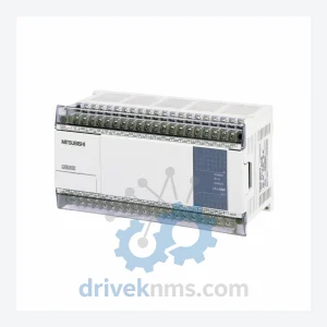
Mitsubishi Electric FX1N-40MC is listed for FX1N Series RFQ review. Confirm quantity, condition and destination before quotation.
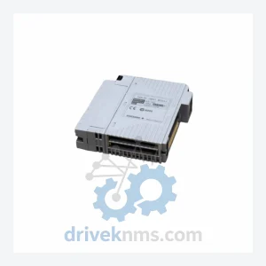
Mitsubishi Electric F2-32RM JY331A401D is listed for Servo Drives RFQ review. Confirm quantity, condition and destination before quotation.