
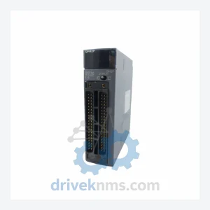
Mitsubishi QX48Y57 BD627B662G51 Combination Unit – PLC Module
Mitsubishi Electric QX48Y57 BD627B662G51 is listed for Servo Drives RFQ review. Confirm quantity, condition and destination before quotation.
RFQ-ready industrial model
Model: SD2DYE-A/SD-2DYE-05
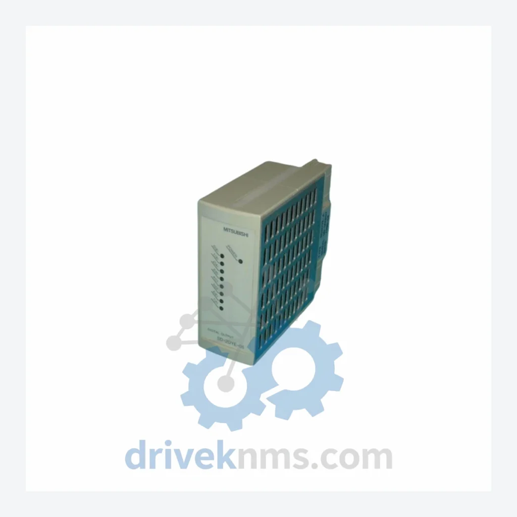
Product Overview
Commercial availability is handled through direct RFQ, model verification and export-oriented follow-up rather than public cart checkout.
Datasheet Preview
Use attached product manuals when available. If the manual is not public yet, request the full file directly through RFQ.
Commercial Path
Product pages on DRIVEKNMS are designed to verify model, brand and series first, then move the buyer into one clean quotation path.
Technical Dossier
The Mitsubishi Electric MELSEC-SD series represents a compact, high-density programmable logic controller platform deployed across global heavy industry sectors including petrochemical refineries, nuclear power auxiliary systems, steel processing lines, and continuous chemical manufacturing. The SD series occupies the mid-tier of Mitsubishi's MELSEC architecture, positioned between the entry-level FX family and the high-availability Q/iQ-R platforms. Its modular backplane design, deterministic scan cycle performance, and broad I/O density made it a standard specification in plant-floor automation projects throughout the 1990s and early 2000s. Installed base remains significant across Asia-Pacific, the Middle East, and Eastern Europe, where long-lifecycle plant assets continue to operate on original control hardware.
The MELSEC-SD series was introduced as part of Mitsubishi Electric's second-generation modular PLC strategy, succeeding the MELSEC-A series and running in parallel with the MELSEC-AnS compact line. The SD platform standardized on a 5V DC backplane bus with a proprietary high-speed serial link (MELSECNET/MINI-S3) for distributed I/O expansion. Early revisions used mask ROM-based CPU firmware, limiting field upgradability; later revisions introduced EEPROM-based parameter storage and battery-backed SRAM for program retention.
Compatibility constraints are a primary maintenance concern for SD-series installations. The SD CPU modules are not pin-compatible with MELSEC-Q or iQ-R base units. I/O modules from the AnS series share physical form factor but differ in bus signaling voltage tolerances, requiring verification before cross-substitution. Communication adapter modules (e.g., SD-A1SJ71UC24-R2) use RS-232C/RS-422 interfaces that predate modern Ethernet-based SCADA integration, necessitating protocol converters in retrofit projects. As of 2026, the MELSEC-SD series is classified as End-of-Life (EOL) by Mitsubishi Electric, with no new production. Spare parts availability depends entirely on secondary market inventory and authorized refurbishment channels.
CPU / Controller Modules
Digital Input (DI) Modules
Digital Output (DO) Modules
Analog I/O (AI/AO) Modules
Communication & Network Modules
Power Supply Modules
MELSEC-SD modules present specific test challenges due to their proprietary backplane bus protocol and battery-dependent program retention. DriveKNMS applies the following verification procedures to all SD-series units prior to shipment:
Continue The Model Path
Move from this exact model into the matching system hub, brand archive, model-family archive or lifecycle sourcing route before sending a final RFQ list.
Related Paths
Mitsubishi Electric QX48Y57 BD627B662G51 is listed for Servo Drives RFQ review. Confirm quantity, condition and destination before quotation.
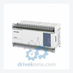
Mitsubishi Electric FX1N-40MC is listed for FX1N Series RFQ review. Confirm quantity, condition and destination before quotation.
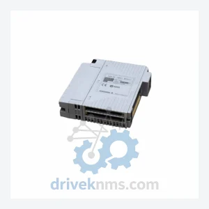
Mitsubishi Electric F2-32RM JY331A401D is listed for Servo Drives RFQ review. Confirm quantity, condition and destination before quotation.