
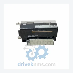
Omron XWT-ID16
Omron XWT-ID16 is listed for Servo Drives RFQ review. Confirm quantity, condition and destination before quotation.
RFQ-ready industrial model
Model: CQM1-CPU43-V1
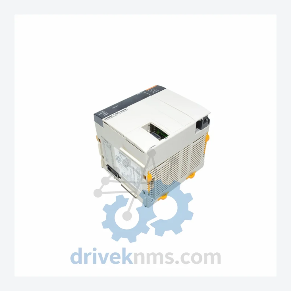
Product Overview
Commercial availability is handled through direct RFQ, model verification and export-oriented follow-up rather than public cart checkout.
Datasheet Preview
Use attached product manuals when available. If the manual is not public yet, request the full file directly through RFQ.
Commercial Path
Product pages on DRIVEKNMS are designed to verify model, brand and series first, then move the buyer into one clean quotation path.
Technical Dossier
Q: How are RFQ terms confirmed?
A: Quantity, required condition, documentation needs, destination and sourcing route are confirmed during RFQ review before quotation.
The CQM1 series was designed around a single-rack, fixed-backplane architecture where the CPU unit integrates the power supply, processor, and I/O bus controller into one housing. Early CPU variants such as the CQM1-CPU11-E and CQM1-CPU21-E provided limited program memory (4K–8K steps) and basic I/O capacity, targeting simple machine control. The V1 revision series — including the CQM1-CPU43-V1 and CQM1-CPU45-V1 — introduced expanded program memory (up to 32K steps), extended data memory (DM), and enhanced instruction sets including floating-point arithmetic and PID control, positioning the CQM1 for more complex process applications.
Communication architecture evolved from RS-232C host link (SYSMAC WAY) in early units to peripheral port + RS-232C dual-port configurations in later CPUs, enabling simultaneous programming terminal connection and host computer supervision. The addition of dedicated communication adapter modules (e.g., CQM1-SCB41-V1) extended the platform to DeviceNet and CompoBus/S fieldbus networks, aligning the CQM1 with distributed I/O architectures prevalent in the late 1990s. The CQM1H series subsequently replaced the CQM1 with an enhanced inner board slot for function expansion, though the CQM1 backplane and I/O modules are not cross-compatible with CQM1H inner board accessories. Facilities migrating from CQM1 to current OMRON NX/NJ or CP2E platforms must account for full I/O rewiring and program conversion, as no direct migration path exists.
CPU Units
Digital Input Modules
Digital Output Modules
Analog & Special Function Modules
Communication & Adapter Modules
The CQM1 backplane bus operates at 5V DC internal logic with a proprietary parallel I/O bus protocol. Quality verification for CQM1 modules at DriveKNMS follows a structured test protocol:
Continue The Model Path
Move from this exact model into the matching system hub, brand archive, model-family archive or lifecycle sourcing route before sending a final RFQ list.
Related Paths
Omron XWT-ID16 is listed for Servo Drives RFQ review. Confirm quantity, condition and destination before quotation.
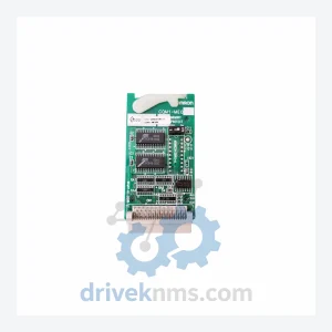
Omron CQM1-ME04K CQM1-ME08K is listed for CQM1 Series RFQ review. Confirm quantity, condition and destination before quotation.
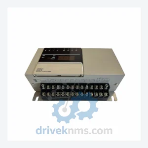
Omron H8PR-16 is listed for Servo Drives RFQ review. Confirm quantity, condition and destination before quotation.