
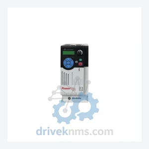
Allen-Bradley PowerFlex 525 AC Drives – 25B-D010N104
Allen-Bradley 25B-D010N104 is listed for PowerFlex 525 RFQ review. Confirm quantity, condition and destination before quotation.
RFQ-ready industrial model
Model: 25B-D6P0N114
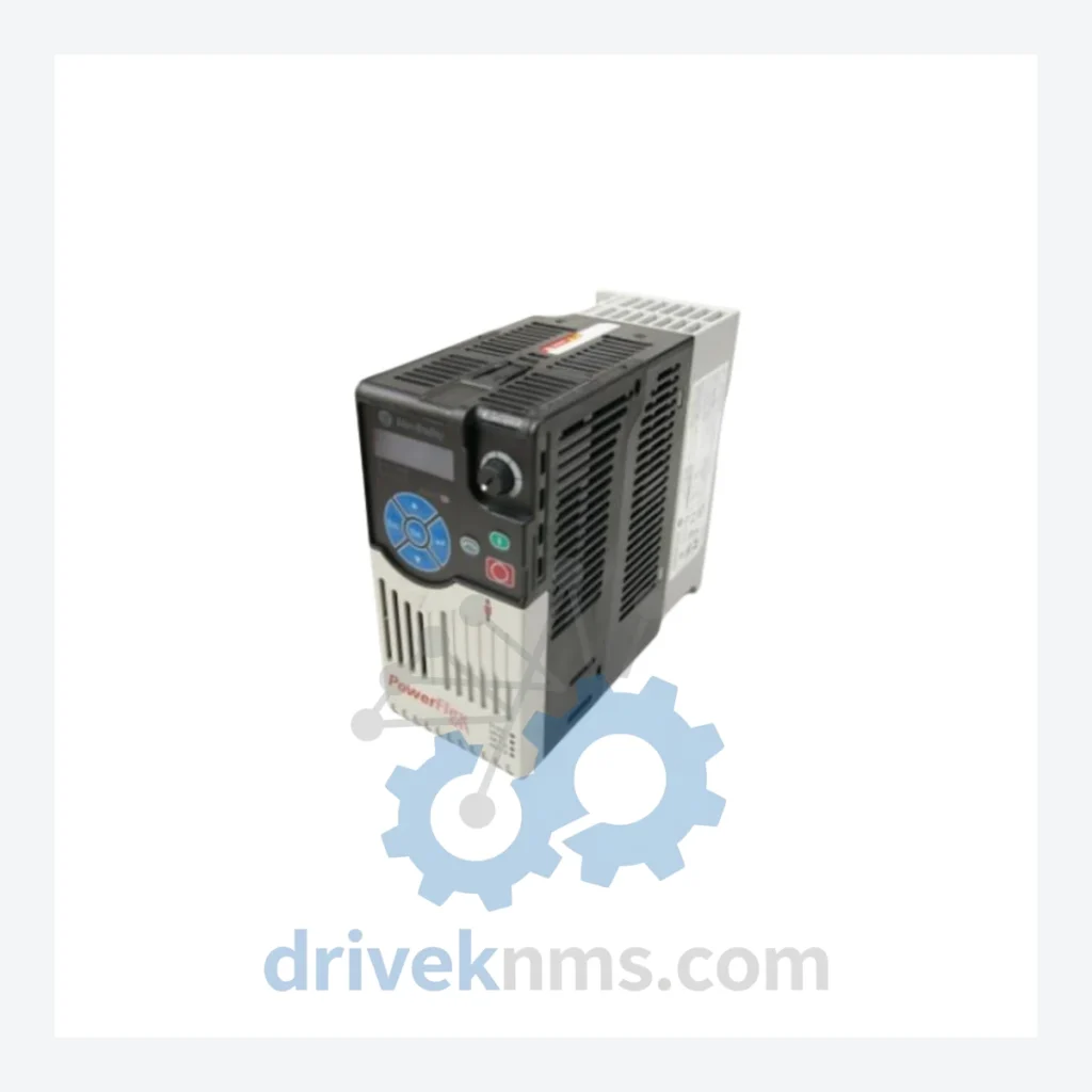
Product Overview
Commercial availability is handled through direct RFQ, model verification and export-oriented follow-up rather than public cart checkout.
Datasheet Preview
Use attached product manuals when available. If the manual is not public yet, request the full file directly through RFQ.
Commercial Path
Product pages on DRIVEKNMS are designed to verify model, brand and series first, then move the buyer into one clean quotation path.
Technical Dossier
The PowerFlex 525 succeeded the PowerFlex 523 (25A prefix) and PowerFlex 4M within Rockwell Automation's compact drive portfolio. Introduced circa 2012, the 25B platform introduced a significant architectural departure from its predecessors: a removable control module (the "control pod") that separates the control electronics from the power section, enabling field replacement without full drive swap. This modular design addressed a key maintenance pain point in the 520 series predecessor (PowerFlex 40/40P) where control and power sections were integrated.
The 525 introduced native dual-port EtherNet/IP as standard, eliminating the need for external communication adapters required on earlier drives such as the PowerFlex 40 (22B) and PowerFlex 400 (22C). Firmware evolution across major revisions (v1.x through v7.x) added features including Logix-based motion integration, enhanced PID control, and expanded Safe Torque Off (STO) certification. The drive communicates via the Common Industrial Protocol (CIP) and is fully compatible with Studio 5000 Logix Designer for parameter management and drive commissioning.
The following catalog numbers represent verified, commonly deployed PowerFlex 525 configurations. Each entry reflects a distinct voltage/current/enclosure/option combination as defined in Allen-Bradley publication 520-SG001.
25B-D6P0N114: 480V 3-phase, 6.0A, IP20/NEMA 1, No HIM, EtherNet/IP dual-port, STO — 3 HP standard frame drive, the subject SKU of this listing.
25B-D2P3N104: 480V 3-phase, 2.3A, IP20/NEMA 1, No HIM, standard I/O — 1 HP entry-level configuration.
25B-D4P0N104: 480V 3-phase, 4.0A, IP20/NEMA 1, No HIM — 2 HP general-purpose variant.
25B-D010N104: 480V 3-phase, 10.5A, IP20/NEMA 1, No HIM — 5 HP mid-range drive.
25B-D013N104: 480V 3-phase, 13.0A, IP20/NEMA 1, No HIM — 7.5 HP standard frame.
25B-D017N104: 480V 3-phase, 17.5A, IP20/NEMA 1, No HIM — 10 HP high-current variant.
25B-D024N104: 480V 3-phase, 24.0A, IP20/NEMA 1, No HIM — 15 HP heavy-duty frame.
25B-D030N104: 480V 3-phase, 30.0A, IP20/NEMA 1, No HIM — 20 HP top-of-range 25B frame.
25B-A8P0N104: 120V 1-phase, 8.0A, IP20/NEMA 1, No HIM — single-phase input, 1 HP.
25B-B2P5N104: 240V 1-phase, 2.5A, IP20/NEMA 1, No HIM — 0.5 HP compact single-phase.
25B-B5P0N104: 240V 1-phase, 5.0A, IP20/NEMA 1, No HIM — 1 HP single-phase variant.
25B-B8P0N104: 240V 1-phase, 8.0A, IP20/NEMA 1, No HIM — 2 HP single-phase drive.
25B-D6P0N114-V: 480V 3-phase, 6.0A, IP20/NEMA 1, with conformal coating — corrosion-resistant variant for harsh environments.
25B-D6P0N114-ND: 480V 3-phase, 6.0A, IP20/NEMA 1, No HIM, no drive option — base power section only.
25B-D010N114: 480V 3-phase, 10.5A, IP20/NEMA 1, EtherNet/IP dual-port, STO — 5 HP with full network and safety options.
25B-D013N114: 480V 3-phase, 13.0A, IP20/NEMA 1, EtherNet/IP dual-port, STO — 7.5 HP networked safety variant.
25B-D017N114: 480V 3-phase, 17.5A, IP20/NEMA 1, EtherNet/IP dual-port, STO — 10 HP full-option configuration.
Each PowerFlex 525 unit processed by DriveKNMS undergoes a structured inspection and functional test protocol specific to the 25B platform architecture. The control module is tested independently from the power section, reflecting the drive's modular design. Key test procedures include: DC bus capacitor ESR measurement, IGBT gate drive integrity check, STO circuit continuity and response-time verification, EtherNet/IP port communication handshake test, and full no-load run test across the drive's rated frequency range (0–400 Hz output). For units with the dual-port EtherNet/IP option (suffix -N114), DLR (Device Level Ring) topology compatibility is verified. Parameter memory is cleared and reset to factory defaults prior to shipment unless the customer specifies a pre-configured parameter file.
Continue The Model Path
Move from this exact model into the matching system hub, brand archive, model-family archive or lifecycle sourcing route before sending a final RFQ list.
Related Paths
Allen-Bradley 25B-D010N104 is listed for PowerFlex 525 RFQ review. Confirm quantity, condition and destination before quotation.
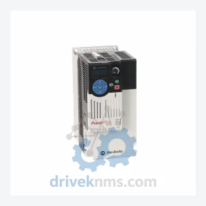
Allen-Bradley 25B-D013N104 is listed for PowerFlex 525 RFQ review. Confirm quantity, condition and destination before quotation.
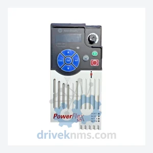
Allen-Bradley 25B-D6P0N104 is listed for PowerFlex 525 RFQ review. Confirm quantity, condition and destination before quotation.