
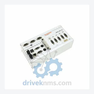
PLEIGER PPC-IPC-S Flash Card – Obsolete PPC Series Spare Part
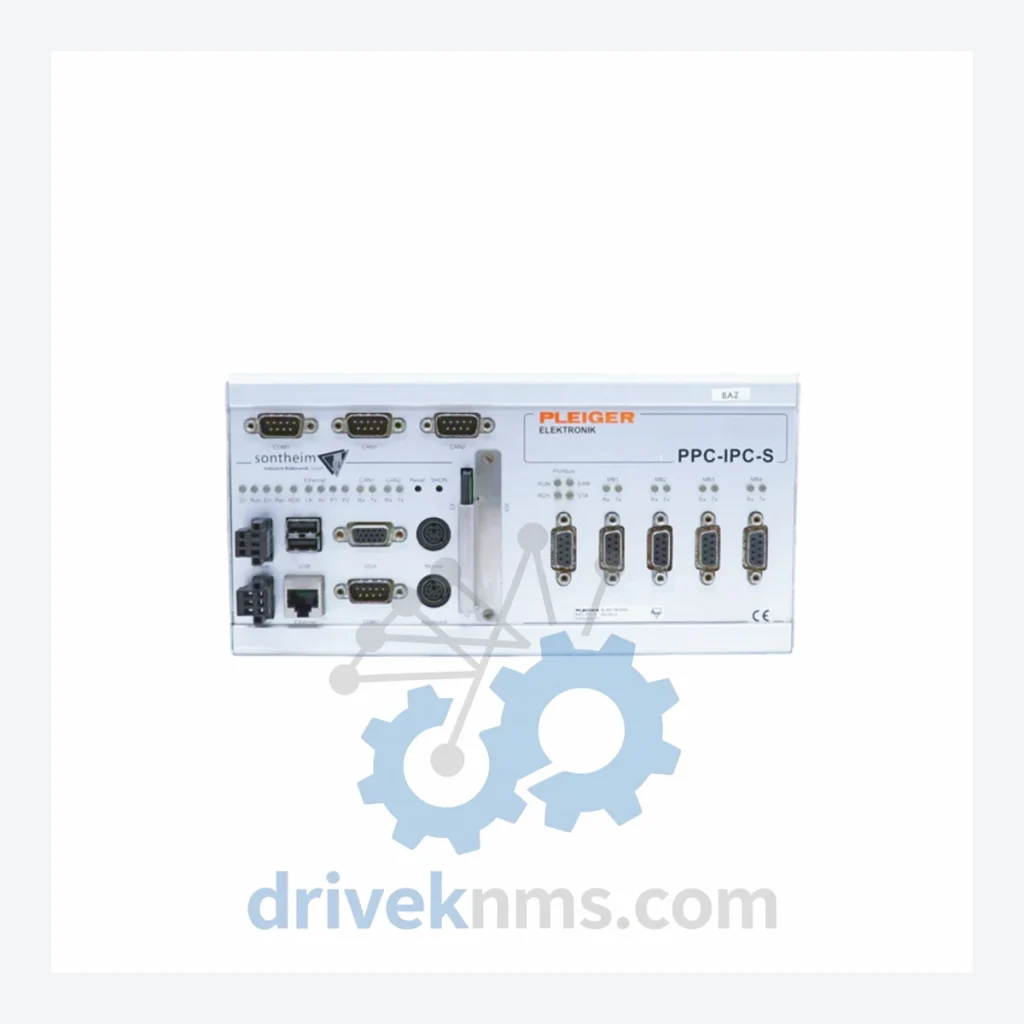
Pleiger PPC-IPC-S is listed for Servo Drives RFQ review. Confirm quantity, condition and destination before quotation.
RFQ-ready industrial model
Model: PPC-IPC-S2
Product Overview
Commercial availability is handled through direct RFQ, model verification and export-oriented follow-up rather than public cart checkout.
Datasheet Preview
Use attached product manuals when available. If the manual is not public yet, request the full file directly through RFQ.
Commercial Path
Product pages on DRIVEKNMS are designed to verify model, brand and series first, then move the buyer into one clean quotation path.
Technical Dossier
The PPC-IPC platform was developed by PLEIGER as a successor to relay-logic and early PLC-based valve control panels. The architecture centers on an embedded PC core running a real-time operating system, interfaced with modular I/O racks that communicate over a proprietary backplane bus. Early revisions of the series used ISA-bus expansion for analog and digital I/O; subsequent generations migrated to a compact PCI (cPCI) and later proprietary slot architecture to improve vibration resistance and hot-swap capability in marine environments.
The S-series designation (e.g., PPC-IPC-S2) identifies the second-generation chassis variant, which introduced enhanced EMC shielding, wider operating temperature tolerance (typically -20°C to +70°C), and support for redundant power supply modules. Communication interfaces evolved from RS-232/RS-485 serial links to include PROFIBUS-DP, Modbus RTU/TCP, and in later firmware revisions, OPC-UA endpoints for integration with modern SCADA and DCS layers. Compatibility between S1 and S2 chassis generations is limited at the backplane level; I/O modules are generally cross-compatible within the same electrical specification class, but firmware versions must be verified before substitution.
The following SKUs represent verified components within the PLEIGER PPC-IPC platform. Each entry reflects a distinct functional role within the system architecture.
PPC-IPC-S2: Second-generation PC-based control chassis, core processing unit for valve automation panels.
PPC-IPC-S1: First-generation chassis variant; predecessor to S2 with ISA-bus I/O expansion architecture.
PPC-IPC-CPU: Central processing unit module; executes real-time control logic and manages I/O polling cycles.
PPC-IPC-DI16: 16-channel digital input module; 24 VDC nominal, for limit switch and binary sensor acquisition.
PPC-IPC-DO16: 16-channel digital output module; relay or transistor output for solenoid valve and actuator commands.
PPC-IPC-AI8: 8-channel analog input module; 4–20 mA / 0–10 V configurable, for position feedback and process variables.
PPC-IPC-AO4: 4-channel analog output module; 4–20 mA signal generation for positioner setpoint transmission.
PPC-IPC-COM-DP: PROFIBUS-DP communication adapter; slave interface for integration with Siemens and ABB DCS systems.
PPC-IPC-COM-MB: Modbus RTU/TCP communication module; dual-port serial and Ethernet interface.
PPC-IPC-PSU-24: 24 VDC redundant power supply module; hot-swap capable, for uninterrupted panel operation.
PPC-IPC-PSU-48: 48 VDC power supply variant; used in marine and offshore panel configurations.
PPC-IPC-RACK-8: 8-slot I/O expansion rack; backplane bus carrier for DI, DO, AI, AO modules.
PPC-IPC-RACK-16: 16-slot I/O expansion rack; extended capacity chassis for large valve group panels.
PPC-IPC-HMI-10: 10-inch industrial touchscreen HMI panel; pre-configured for PPC-IPC visualization layer.
PPC-IPC-FW-S2: Firmware package for S2 chassis; includes real-time OS image and valve control application runtime.
PPC-IPC-BAT: CMOS/RTC backup battery module; maintains system clock and SRAM data during power loss.
PPC-IPC-CF-4G: 4 GB CompactFlash storage module; operating system and application data carrier for CPU module.
PLEIGER PPC-IPC modules present specific test challenges due to their integrated backplane communication architecture and mixed analog/digital signal paths. DriveKNMS applies the following verification procedures to all PPC-IPC inventory:
Chassis units (S1, S2) are powered on a bench rig replicating the nominal 24 VDC or 48 VDC supply rail. CPU modules are booted to firmware initialization and verified for POST completion and backplane bus enumeration. Digital I/O modules are tested under load using a dedicated stimulus/response fixture that exercises all 16 channels individually, confirming correct switching thresholds and output drive capability. Analog modules are calibrated against a traceable reference standard; linearity and offset errors are recorded and must fall within the original PLEIGER specification tolerance (typically ±0.1% full scale). Communication modules are tested for protocol handshake integrity using a PROFIBUS or Modbus master simulator. Power supply modules are load-tested at 100% rated current and verified for output voltage stability and overcurrent protection response. All tested units receive a condition report and are tagged with test date and technician ID prior to shipment.
Continue The Model Path
Move from this exact model into the matching system hub, brand archive, model-family archive or lifecycle sourcing route before sending a final RFQ list.
Related Paths
Pleiger PPC-IPC-S is listed for Servo Drives RFQ review. Confirm quantity, condition and destination before quotation.
Alstom MVAJ105RA0802A is listed for MiCOM Series RFQ review. Confirm quantity, condition and destination before quotation.
Moore 16137-174 is listed for Servo Drives RFQ review. Confirm quantity, condition and destination before quotation.