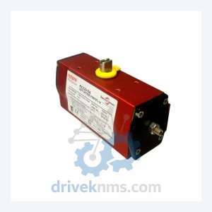
Rotork RC220-SR087 Actuator F05F07-14 – Obsolete RC Series Spare Part
Rotork RC220-SR087 Actuator F05F07-14 – Obsolete RC Series Spare Part When a Rotork RC220-SR087 actuator fails in a live process…
Model: MOD 6G
Product Overview
Commercial availability is handled through direct RFQ, model verification and export-oriented follow-up rather than public cart checkout.
Datasheet Preview
Use attached product manuals when available. If the manual is not public yet, request the full file directly through RFQ.
Commercial Path
Product pages on DRIVEKNMS are designed to verify model, brand and series first, then move the buyer into one clean quotation path.
Technical Dossier
The Rotork MOD Series represents one of the most widely deployed actuator control and monitoring module families in global heavy industry. Installed across petrochemical complexes, nuclear power stations, offshore platforms, and crude oil refineries, MOD Series modules serve as the primary interface layer between field-mounted electric actuators and plant-level DCS/SCADA systems. The series is engineered to IEC 60068 environmental standards and is rated for continuous operation in Class I hazardous area installations. Its modular backplane architecture allows hot-swap replacement of individual function cards without full system shutdown — a critical requirement in continuous-process industries where unplanned downtime carries six-figure hourly cost penalties. The MOD platform is recognized by major EPC contractors (Bechtel, Technip, Wood Group) as a preferred actuator interface standard, with installed base spanning over 40 countries.
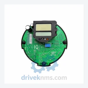
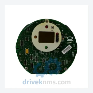
The Rotork MOD Series was introduced as a successor to the earlier A-Range and IQ-Range standalone control modules, consolidating distributed actuator intelligence into a rack-mounted, bus-addressable format. Early-generation MOD hardware (MOD 1x, MOD 2x) used parallel wiring topologies and proprietary RS-485 derivatives for inter-module communication. The MOD 3x generation introduced HART protocol compatibility, enabling integration with asset management platforms such as Emerson AMS and Honeywell FSC. The MOD 5x and MOD 6x generations represent the current mature architecture, incorporating dual-redundant power rails, CAN bus backplane communication, and optional Profibus DP / Modbus RTU field network adapters. Compatibility between generations requires careful attention: MOD 6x CPU cards are not backward-compatible with MOD 3x backplanes without a firmware bridge adapter. As of 2024, Rotork has formally classified MOD 1x and MOD 2x hardware as End-of-Life (EOL), with MOD 3x entering the Mature/Sustained phase. MOD 5x and MOD 6x remain in active production. For plants operating legacy MOD 2x or MOD 3x infrastructure, third-party lifecycle extension suppliers such as DriveKNMS provide tested replacement boards and cross-reference mapping to current equivalents.
The following SKUs represent verified, commonly sourced components within the Rotork MOD Series. Each module is classified by functional category.
CPU / Controller Modules
Digital Input (DI) Modules
Digital Output (DO) Modules
Analog Input / Output (AI/AO) Modules
Communication / Network Adapter Modules
Power Supply Modules
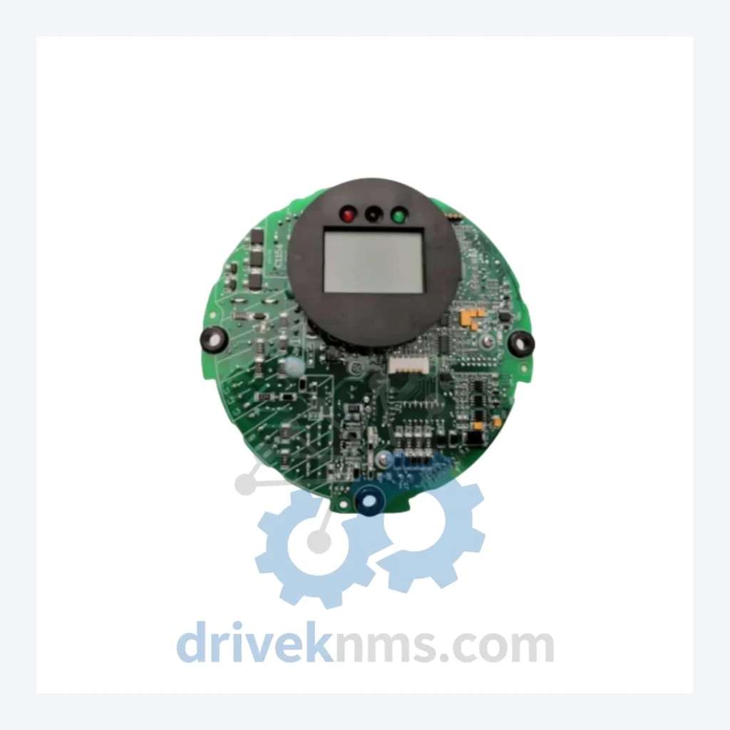
MOD Series modules present specific test challenges due to their multi-layer backplane bus architecture and mixed analog/digital signal paths. DriveKNMS applies the following verification protocol to all MOD Series units prior to dispatch: (1) Visual inspection for PCB delamination, capacitor bulge, and connector pin corrosion — common failure modes in units recovered from high-humidity or coastal installations. (2) Powered functional test on a dedicated MOD-compatible test rack, verifying backplane CAN bus communication, I/O channel continuity, and LED status indication. (3) For CPU modules (MOD 6G, MOD 5G, MOD 3G): firmware version verification and EEPROM integrity check. (4) For analog modules: calibration verification against a traceable 4–20 mA reference source, with channel-by-channel linearity confirmation. (5) Burn-in cycle: 48-hour continuous operation at 40°C ambient to screen for early-life failures. All test results are documented and shipped with each unit. Units that fail any stage of the protocol are quarantined and not offered for sale.
© 2026 DriveKNMS. All trademarks belong to their respective owners. Specifications are for reference only and subject to change without notice. Verify all parameters against official documentation before installation.
Related Paths
Rotork RC220-SR087 Actuator F05F07-14 – Obsolete RC Series Spare Part When a Rotork RC220-SR087 actuator fails in a live process…
Rotork IQT MOD6G: Sourcing Strategy & Asset Return Value in a Constrained Global Supply Chain The Rotork IQT MOD6G is…
ROTORK IQ/IQT Series: Comprehensive Module Range and Technical Overview The ROTORK IQ and IQT series of electric valve actuators and…