
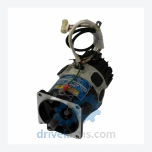
Sanyo Denki L720-012EL8 DC Servo Motor – Obsolete L-Series Spare Part
Sanyo Denki L720-012EL8 is listed for Servo Drives RFQ review. Confirm quantity, condition and destination before quotation.
RFQ-ready industrial model
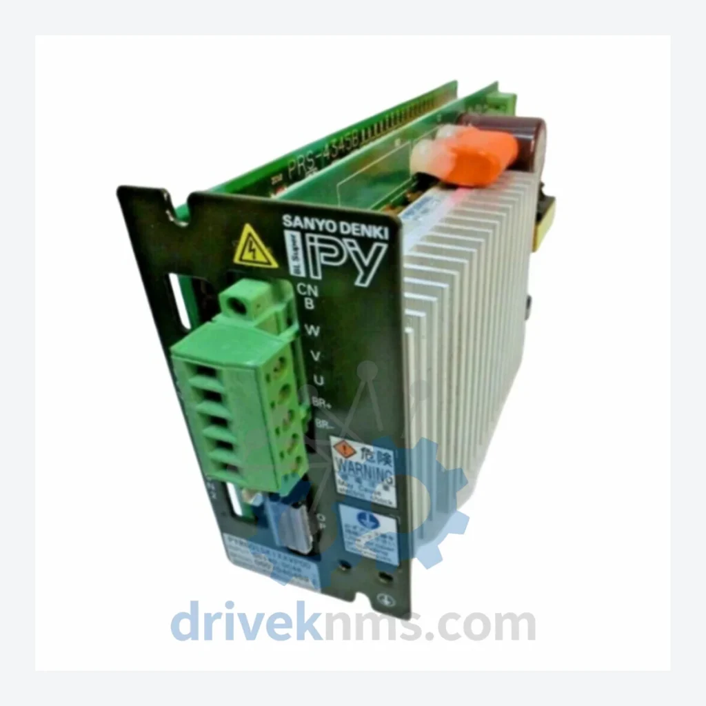
Model: PYRG015K1XXVP00
Product Overview
Commercial availability is handled through direct RFQ, model verification and export-oriented follow-up rather than public cart checkout.
Datasheet Preview
Use attached product manuals when available. If the manual is not public yet, request the full file directly through RFQ.
Commercial Path
Product pages on DRIVEKNMS are designed to verify model, brand and series first, then move the buyer into one clean quotation path.
Technical Dossier
DriveKNMS reviews sourcing options for this model through RFQ handling before quotation.
Note: Electrical parameters such as rated current, input voltage range, and encoder interface specifications vary by configuration suffix. Confirmed parameters are provided upon request with unit verification. No parameters are stated here that have not been independently verified.
The practical consequence: when a PYRG015K1XXVP00 fails, the realistic options are (1) source an identical replacement, or (2) undertake a partial system redesign. Option 2 is rarely as straightforward as vendors of replacement platforms suggest. Hidden costs include updated wiring harnesses, revised PLC ladder logic, operator retraining, and re-validation of the machine's output quality — all before the line produces a single conforming part.
Facilities that have navigated this situation consistently report the same conclusion: maintaining a dedicated spare of the exact amplifier model is the lowest-cost risk mitigation available. The carrying cost of one spare unit is a fraction of a single day's lost production for most installations.
Extending Asset Life 5–10 Years Through Strategic Spare Parts Management
For plant managers facing pressure to defer capital expenditure on new automation platforms, a structured spare parts strategy for existing Sanyo Denki PY-series installations can realistically extend productive asset life by five to ten years. The approach is straightforward in principle but requires discipline in execution:
1. Failure mode mapping. Identify which components in the drive system have historically failed first — typically the amplifier's power stage, the encoder feedback interface, or the regenerative braking circuit. The PYRG015K1XXVP00 sits at the center of this failure map for its motor class.
2. Criticality-weighted stocking. Not every spare needs to be held on-site. The amplifier, however, qualifies as a Tier 1 critical spare — the component whose absence causes immediate line stoppage with no workaround. One unit on the shelf is the minimum defensible position for any facility running this drive in a single-point-of-failure configuration.
3. Condition monitoring cadence. Servo amplifiers in continuous-duty applications accumulate thermal stress on electrolytic capacitors and IGBT modules. A scheduled inspection every 18–24 months — checking for capacitor bulge, bus voltage ripple, and thermal interface degradation — allows planned replacement before failure, not after.
4. Firmware and parameter documentation. Before any amplifier is replaced, the existing parameter set must be recorded. This is a five-minute task that eliminates hours of re-commissioning time. Many facilities discover this requirement only after a failure, when the original unit is no longer readable.
These four practices, applied consistently, are what separate facilities that manage aging automation assets from those that are managed by them.
Every PYRG015K1XXVP00 unit processed by DriveKNMS passes a structured five-stage quality protocol before it is offered for sale:
Stage 1 – Electrolytic Capacitor Assessment. Capacitor aging is the primary failure mechanism in servo amplifiers that have been in storage or light service. Each unit is inspected for physical deformation, and where test equipment permits, capacitance and ESR are measured against manufacturer tolerances.
Stage 2 – Firmware Version Verification. The firmware revision is recorded and cross-referenced against known compatibility requirements for the target application where that information is available from the customer.
Stage 3 – Pin and Connector Inspection. All I/O connectors, encoder feedback ports, and power terminals are inspected under magnification for corrosion, fretting, and mechanical damage. Affected contacts are cleaned or flagged for disclosure.
Stage 4 – Functional Bench Test. Where test fixtures are available for the specific amplifier configuration, units are powered and basic drive response is verified prior to shipment.
Stage 5 – Packaging and Documentation. Units are packaged in ESD-protective materials with desiccant. Condition grade and any noted observations are documented and provided to the buyer.
Q: How do I know the unit is genuine and not counterfeit?
A: All units are sourced through documented supply channels. Physical markings, label format, and board construction are verified against known-good references. Customers are encouraged to request photos of the specific unit prior to purchase.
Continue The Model Path
Move from this exact model into the matching system hub, brand archive, model-family archive or lifecycle sourcing route before sending a final RFQ list.
Related Paths
Sanyo Denki L720-012EL8 is listed for Servo Drives RFQ review. Confirm quantity, condition and destination before quotation.
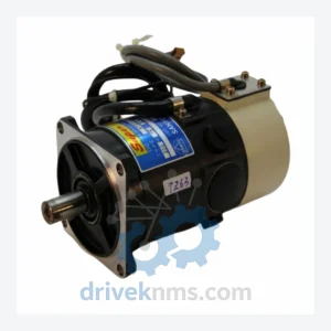
Sanyo Denki R720-012E18 E681000C30 is listed for Servo Drives RFQ review. Confirm quantity, condition and destination before quotation.
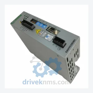
Sanyo Denki PMAPA1S6B01 is listed for Servo Drives RFQ review. Confirm quantity, condition and destination before quotation.