
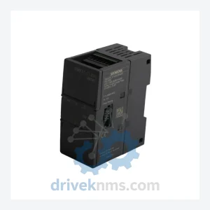
Siemens S7-200 SMART Modules – 6ES7288-3AR02-0AA0
Siemens 6ES7288-3AR02-0AA0 is listed for S7-200 SMART RFQ review. Confirm quantity, condition and destination before quotation.
RFQ-ready industrial model
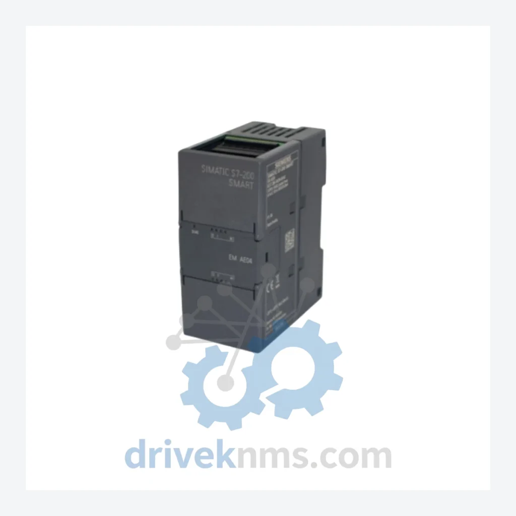
Model: 6ES7288-3AE04-0AA0
Product Overview
Commercial availability is handled through direct RFQ, model verification and export-oriented follow-up rather than public cart checkout.
Datasheet Preview
Use attached product manuals when available. If the manual is not public yet, request the full file directly through RFQ.
Commercial Path
Product pages on DRIVEKNMS are designed to verify model, brand and series first, then move the buyer into one clean quotation path.
Technical Dossier
The S7-200 SMART was introduced by Siemens circa 2012 as a direct replacement for the S7-200 (Classic) series, which had been in production since the mid-1990s. The Classic series used the MPI/PPI communication protocol and relied on the STEP 7 Micro/WIN programming environment. The SMART generation introduced PROFINET Ethernet as the primary communication interface, replaced the programming environment with STEP 7 Micro/WIN SMART, and expanded the CPU's onboard I/O capacity.
Architecturally, the S7-200 SMART uses a modular backplane-less design: expansion modules connect via a direct bus connector on the left side of the CPU, forming a daisy-chain up to six expansion modules deep. This design eliminates backplane failure modes common in rack-based systems but requires strict attention to module sequencing and power budgeting. Early firmware revisions (V1.x) had known compatibility constraints with certain EM signal board combinations; V2.x and later resolved most inter-module communication timing issues. Engineers maintaining legacy V1.x CPU installations must verify firmware compatibility before substituting expansion modules from later production batches.
The S7-200 SMART series is currently in its mature/end-of-active-development phase. Siemens has positioned the S7-1200 as the strategic successor for new designs. However, the S7-200 SMART remains in active production and Siemens continues to provide spare parts and firmware support, making lifecycle extension a viable strategy for existing installations through at least 2030.
The following SKUs represent verified, commonly stocked modules within the S7-200 SMART ecosystem, classified by functional category:
CPU Modules (Standard & RELAY Output)
6ES7288-1SR20-0AA0: CPU SR20 — 12 DI / 8 DO relay, 20 I/O onboard, 12KB program memory.
6ES7288-1SR30-0AA0: CPU SR30 — 18 DI / 12 DO relay, 30 I/O onboard, 18KB program memory.
6ES7288-1SR40-0AA0: CPU SR40 — 24 DI / 16 DO relay, 40 I/O onboard, 24KB program memory.
6ES7288-1SR60-0AA0: CPU SR60 — 36 DI / 24 DO relay, 60 I/O onboard, 30KB program memory.
6ES7288-1ST20-0AA0: CPU ST20 — 12 DI / 8 DO transistor (sourcing), 20 I/O onboard.
6ES7288-1ST30-0AA0: CPU ST30 — 18 DI / 12 DO transistor (sourcing), 30 I/O onboard.
6ES7288-1ST40-0AA0: CPU ST40 — 24 DI / 16 DO transistor (sourcing), 40 I/O onboard.
6ES7288-1ST60-0AA0: CPU ST60 — 36 DI / 24 DO transistor (sourcing), 60 I/O onboard.
Digital Input / Output Expansion Modules (EM DI / DO)
6ES7288-2DE08-0AA0: EM DE08 — 8-channel 24VDC digital input expansion module.
6ES7288-2DR08-0AA0: EM DR08 — 8-channel relay digital output expansion module.
6ES7288-2DT08-0AA0: EM DT08 — 8-channel transistor digital output expansion module.
6ES7288-2DR16-0AA0: EM DR16 — 8 DI / 8 DO relay mixed digital I/O expansion module.
Analog Input / Output Expansion Modules (EM AI / AO)
6ES7288-3AE04-0AA0: EM AE04 — 4-channel analog input module; supports ±10V, 0–10V, 0–20mA, 4–20mA; 12-bit resolution; current/voltage selectable per channel via DIP switch.
6ES7288-3AQ02-0AA0: EM AQ02 — 2-channel analog output module; 0–10V / 0–20mA / 4–20mA output; 12-bit resolution.
6ES7288-3AM06-0AA0: EM AM06 — 4 AI / 2 AO mixed analog I/O module; combined input/output for compact panel designs.
Communication & Specialty Modules
6ES7288-5BA01-0AA0: SB CM01 — RS485/RS232 signal board; mounts directly on CPU face; adds serial communication port without consuming expansion slot.
6ES7288-5AE01-0AA0: SB AE01 — 1-channel analog input signal board; 12-bit; mounts on CPU face.
6ES7288-5AQ01-0AA0: SB AQ01 — 1-channel analog output signal board; 12-bit; mounts on CPU face.
6ES7288-5DT04-0AA0: SB DT04 — 2 DI / 2 DO transistor signal board; mounts on CPU face.
For installations where the S7-200 SMART CPU firmware is locked to a specific expansion module hardware revision, DriveKNMS can source modules by production date code upon request.
All S7-200 SMART modules processed by DriveKNMS undergo a structured inspection and functional verification protocol prior to dispatch:
- Visual inspection: PCB examination for corrosion, burn marks, capacitor bulge, and connector pin integrity. Bus connector pins on expansion modules are inspected under magnification for deformation.
- Power-on test: Module is powered via a calibrated 24VDC bench supply. LED status indicators are verified against Siemens diagnostic specifications.
- Functional I/O test (analog modules): For the 6ES7288-3AE04-0AA0 and similar analog modules, each channel is stimulated with a calibrated signal source (voltage and current modes independently). ADC output values are read via a test CPU and compared against Siemens published accuracy specifications (±0.5% full scale for voltage, ±0.5% for current at 25°C ambient).
- Communication bus verification: Expansion bus connector is tested for correct impedance and signal integrity using a reference CPU in loopback configuration.
- Firmware version logging: Where accessible, CPU module firmware version is recorded and disclosed to the buyer prior to shipment.
Continue The Model Path
Move from this exact model into the matching system hub, brand archive, model-family archive or lifecycle sourcing route before sending a final RFQ list.
Related Paths
Siemens 6ES7288-3AR02-0AA0 is listed for S7-200 SMART RFQ review. Confirm quantity, condition and destination before quotation.
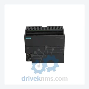
Siemens 6ES7288-1SR40-0AA0 is listed for S7-200 SMART RFQ review. Confirm quantity, condition and destination before quotation.

Siemens 6ES7288-7DP01-0AA0 is listed for S7-200 SMART RFQ review. Confirm quantity, condition and destination before quotation.