Technical Dossier
Product Details And Specifications
Siemens SIMATIC S7-400 Series Technical Notes
The Evolution of S7-400 Architecture
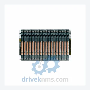
The SIMATIC S7-400 platform was introduced in the mid-1990s as the successor to the S5-115U/H and S5-135U/155U families. Its architecture is built around a passive backplane bus (P-bus and K-bus) housed in UR1, UR2, ER1, and ER2 rack variants, supporting up to 21 slots per rack and multi-rack expansion via IM (Interface Module) pairs.
Early firmware generations (V1.x–V3.x) established the core instruction set and PROFIBUS-DP master integration. The V4.x and V5.x generations introduced expanded memory addressing, PROFINET IO capability on select CPUs, and enhanced H-system synchronization protocols. The V6.x generation, applicable to the 6ES7417-4HL04-0AB0 (firmware V6.0.x), represents the mature phase of the platform, incorporating IEC 61131-3 compliance, S7 communication over Industrial Ethernet, and extended diagnostic buffer depth.
Compatibility considerations are significant for maintenance engineers: S7-400 CPUs are backward-compatible with legacy S7-400 I/O modules but require matching IM firmware versions for multi-rack configurations. Migration from older CPU 414 or CPU 416 variants to CPU 417-4H requires project re-compilation in STEP 7 V5.6 or TIA Portal V16+ with the S7-400 option package. The platform has entered its end-of-mainstream-support phase; Siemens has designated the S7-1500 as the strategic successor, though S7-400 hardware remains in active production for installed-base continuity.
S7-400 Full Catalog & Functionalities (SKU List)
CPU Modules
- 6ES7412-1XJ07-0AB0: CPU 412-1, 256 KB work memory, MPI/DP interface, entry-level S7-400 processor.
- 6ES7414-2XK05-0AB0: CPU 414-2, 512 KB work memory, dual MPI/DP ports, mid-range process controller.
- 6ES7414-3XM07-0AB0: CPU 414-3 PN/DP, 1.4 MB work memory, integrated PROFINET IO controller.
- 6ES7416-2XN07-0AB0: CPU 416-2, 5.6 MB work memory, high-throughput process automation CPU.
- 6ES7416-3XR07-0AB0: CPU 416-3 PN/DP, 5.6 MB work memory, dual PROFINET + DP interfaces.
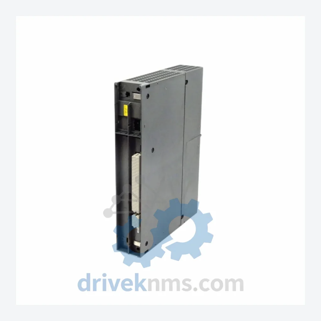
- 6ES7417-4HL04-0AB0: CPU 417-4H, 30 MB work memory, fault-tolerant H-system CPU with fiber-optic sync, redundant rack operation.
- 6ES7417-4HT14-0AB0: CPU 417H V6.1, updated firmware variant of the 417-4H for extended lifecycle support.
Digital Input / Output Modules
- 6ES7421-1BL01-0AA0: SM 421 DI 32×DC 24V, 32-channel digital input, 24 VDC, standard process I/O.
- 6ES7422-1BL00-0AA0: SM 422 DO 32×DC 24V/0.5A, 32-channel digital output, transistor type.
- 6ES7422-1FF00-0AA0: SM 422 DO 16×AC 120/230V/2A, 16-channel relay output for high-voltage actuators.
- 6ES7431-1KF10-0AB0: SM 431 AI 8×13Bit, 8-channel analog input, ±10V / 0–20mA, 13-bit resolution.
- 6ES7432-1HF00-0AB0: SM 432 AO 8×13Bit, 8-channel analog output, voltage/current configurable.
Communication & Interface Modules
- 6ES7460-1BA01-0AB0: IM 460-1 Send, central rack interface module for multi-rack expansion (K-bus).
- 6ES7461-1BA01-0AB0: IM 461-1 Receive, expansion rack interface module, paired with IM 460-1.
- 6GK7443-1EX30-0XE0: CP 443-1, Industrial Ethernet communication processor, TCP/IP, S7 communication.
- 6GK7443-5DX05-0XE0: CP 443-5 Extended, PROFIBUS-DP master/slave communication processor.
Power Supply Modules
- 6ES7407-0DA02-0AA0: PS 407 4A, 24 VDC / 4A regulated power supply for S7-400 racks.
- 6ES7407-0KA02-0AA0: PS 407 10A, 24 VDC / 10A power supply for high-load rack configurations.
- 6ES7407-0RA02-0AA0: PS 407 20A R, 24 VDC / 20A redundant power supply for H-system racks.
Sourcing Hard-to-Find & Obsolete S7-400 Parts
- Discontinued CPU variants (CPU 412, 413, 414, 416 early generations) with verified firmware versions.
- Legacy IM 460/461 interface module pairs for original UR1/UR2 rack configurations.
- End-of-life SM 421/422/431/432 I/O modules with original Siemens part markings.
- Obsolete CP 443-1 and CP 443-5 communication processors with original firmware media.
Quality Control for the S7-400 Range
S7-400 modules present specific test challenges due to their passive backplane bus architecture and the complexity of H-system synchronization logic. DriveKNMS applies the following test protocol to all S7-400 units prior to dispatch:
- Rack-level power-on test: Each module is seated in a reference UR2 rack with a calibrated PS 407 power supply. Bus voltage rails (P5V, P24V, backplane) are verified against Siemens tolerance specifications.
- CPU diagnostic buffer read: For CPU modules, STEP 7 or TIA Portal is used to read the full diagnostic buffer, confirming no latent hardware faults or STOP-state error codes.
- H-system sync verification (CPU 417-4H specific): The 6ES7417-4HL04-0AB0 is tested in a paired H-configuration using fiber-optic sync cables. Master/standby switchover is triggered and cycle-time deviation is measured against Siemens' ≤1 ms synchronization specification.
- I/O channel functional test: All digital and analog I/O channels are exercised at rated voltage/current. Analog modules are calibrated against a traceable reference source.
- Communication port test: MPI, PROFIBUS-DP, and Ethernet ports are verified using protocol analyzers. CP modules are tested for S7 PUT/GET and FETCH/WRITE transaction integrity.
- Firmware version confirmation: Firmware version is read and documented. Downgrade or upgrade paths are noted where applicable to the customer's existing project version.