
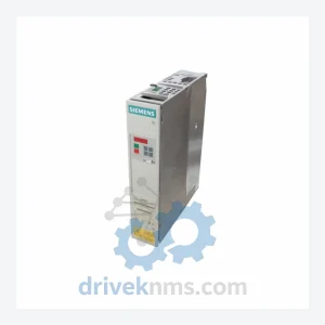
Siemens Simovert Masterdrive 6SE70 Modules: 6SE7018-0TA51-Z
Siemens 6SE7018-0TA51-Z is listed for Simovert Masterdrive 6SE70 RFQ review. Confirm quantity, condition and destination before quotation.
RFQ-ready industrial model
Model: 6SE7022-6TC51-Z

Product Overview
Commercial availability is handled through direct RFQ, model verification and export-oriented follow-up rather than public cart checkout.
Datasheet Preview
Use attached product manuals when available. If the manual is not public yet, request the full file directly through RFQ.
Commercial Path
Product pages on DRIVEKNMS are designed to verify model, brand and series first, then move the buyer into one clean quotation path.
Technical Dossier
The 6SE70 platform evolved through three distinct hardware generations. The first generation (circa 1993–1998) introduced the Compact and chassis-mount form factors with analog setpoint interfaces and basic V/f control. The second generation (1998–2006) added full vector control (VC) and servo control (SC) firmware variants, CAN/PROFIBUS-DP communication boards, and the Technology Option (T) slot for application-specific function blocks. The third generation consolidated the power electronics into higher-density IGBT modules and introduced the CBP2 (PROFIBUS) and CBC (CAN) communication boards as standard accessories.
Compatibility across generations is constrained by the Control Unit (CU) firmware version and the power section hardware revision. Mixing CU versions across major firmware generations (e.g., V1.x with V3.x) requires careful parameter migration. The SIMOVERT Masterdrive entered the Siemens product lifecycle phase of "RFQ availability review" around 2010 and transitioned to "discontinued" status for most variants by 2018, with the SINAMICS G120 and S120 series designated as functional successors. Long-term spare parts support remains critical for plants with 10–25 year remaining operational horizons.
Compact Inverter Units (Chassis / Wall-Mount)
Control Units (CU)
Communication Boards
I/O and Technology Option Boards
Each 6SE70 unit processed by DriveKNMS undergoes a structured test protocol specific to the backplane bus architecture and IGBT gate driver topology of this series. The test sequence includes: incoming visual inspection for capacitor bulge, bus bar corrosion, and IGBT module cracking; DC bus capacitance measurement against OEM specification (tolerance ±10%); insulation resistance test at 500 V DC between power terminals and chassis; functional power-up under no-load conditions with parameter set verification; and dynamic load test at 50% and 100% rated current using a motor simulator. Communication boards (CBP2, CBC) are tested for bus enumeration and cyclic data exchange using a PROFIBUS/CAN master simulator. Units that fail any stage are quarantined and documented; no failed unit is relabeled or re-shipped.
Continue The Model Path
Move from this exact model into the matching system hub, brand archive, model-family archive or lifecycle sourcing route before sending a final RFQ list.
Related Paths
Siemens 6SE7018-0TA51-Z is listed for Simovert Masterdrive 6SE70 RFQ review. Confirm quantity, condition and destination before quotation.
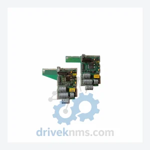
Siemens ULC0065 is listed for Servo Drives RFQ review. Confirm quantity, condition and destination before quotation.
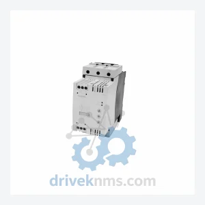
Siemens RW3045-1AB14 is listed for SIRIUS Series RFQ review. Confirm quantity, condition and destination before quotation.