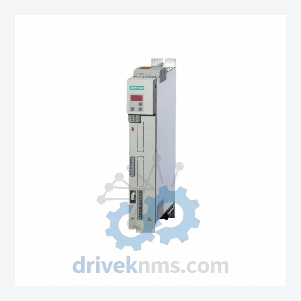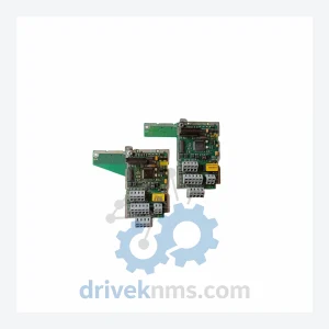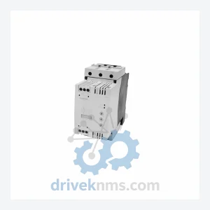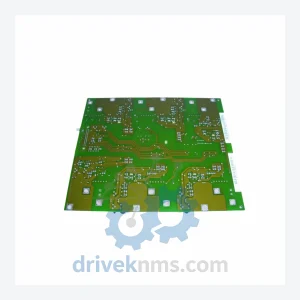
Siemens MASTERDRIVES Modules: 6SE7032-5FB87-2DA1

Model: 6SE7032-5FB87-2DA1

Brand Siemens
Series MASTERDRIVES
Model 6SE7032-5FB87-2DA1
RFQ-ready model route Obsolete and surplus sourcing Export follow-up by model list

Product Overview

Commercial availability is handled through direct RFQ, model verification and export-oriented follow-up rather than public cart checkout.

Datasheet Preview

Datasheet Preview

Use attached product manuals when available. If the manual is not public yet, request the full file directly through RFQ.

Request Full Manual

Commercial Path

Use This Page To Confirm The Model, Then Move To RFQ

Product pages on DRIVEKNMS are designed to verify model, brand and series first, then move the buyer into one clean quotation path.

Technical Dossier

Product Details And Specifications

Siemens MASTERDRIVES Series Technical Notes

The 6SE7032-5FB87-2DA1 is a braking unit within this family, designed to dissipate regenerative energy during rapid deceleration cycles — a critical function in crane drives, winding machines, and centrifuge applications where resistive braking is required to protect the DC bus from overvoltage faults.

The Evolution of MASTERDRIVES Architecture

Siemens introduced the MASTERDRIVES platform in the early 1990s as a successor to the SIMOVERT P and SIMOVERT A families. The architecture was built around a common DC bus concept, enabling multi-axis installations to share regenerative energy between drives rather than dissipating it entirely as heat — a significant efficiency advantage in coordinated multi-motor systems.

The series evolved through several hardware generations:

  • First Generation (6SE70 compact units): Fixed-frame compact inverters with integrated rectifier and inverter stages. Limited communication options, primarily USS protocol via RS485.
  • Second Generation (Chassis/Cabinet units): Modular rectifier-inverter separation. Introduction of the CBP (PROFIBUS) and CBC (CAN) communication boards, enabling integration into distributed control architectures such as Siemens SIMATIC S7 and third-party DCS platforms.
  • Technology Boards (T400, T300): Application-specific technology boards added closed-loop winding, positioning, and synchronization functions directly within the drive, reducing the need for external PLCs in complex motion tasks.
  • Transition to SINAMICS: From approximately 2005 onward, Siemens began migrating new projects to the SINAMICS S120 platform. MASTERDRIVES entered a maintenance-only lifecycle phase. Spare parts availability from OEM channels has progressively declined, making third-party sourcing essential for installed base maintenance.

Compatibility between hardware generations requires careful verification of firmware versions, CU (Control Unit) board revisions, and power section ratings. Mixing incompatible firmware on a shared DC bus can result in synchronization faults and uncontrolled axis behavior.

MASTERDRIVES Full Catalog & Functionalities (SKU List)

The following SKUs represent verified models within the Siemens MASTERDRIVES 6SE70xx family, organized by functional category. Each entry reflects a distinct hardware role within a MASTERDRIVES installation.

Braking Units & Chopper Modules

  • 6SE7032-5FB87-2DA1: Braking unit, 132 kW, for rapid DC bus energy dissipation in crane and winding drives.
  • 6SE7021-0EB87-2DA1: Compact braking unit, lower power range, for standalone inverter braking applications.
  • 6SE7023-4TC87-2DA1: Braking chopper module, chassis format, compatible with common DC bus multi-drive systems.

Rectifier / Active Front End Units

  • 6SE7031-2EF85-0AA0: Uncontrolled rectifier unit, 6-pulse, for standard non-regenerative supply.
  • 6SE7033-2EG85-0AA0: Controlled rectifier, 12-pulse configuration, reduced harmonic distortion for sensitive grid environments.
  • 6SE7036-0EK85-0AA0: Active infeed/regenerative rectifier, enables full four-quadrant operation and energy feedback to grid.

Inverter / Motor Control Units

  • 6SE7022-6EC85-1AA0: Vector control inverter, 11 kW, for high-dynamic torque applications.
  • 6SE7027-2ED85-1AA0: VC inverter, 37 kW, standard chassis format.
  • 6SE7031-8EF85-1AA0: VC inverter, 90 kW, for heavy-duty pump and compressor drives.
  • 6SE7035-1EK85-1AA0: VC inverter, 250 kW, large chassis, common in rolling mill auxiliary drives.

Control & Communication Boards

  • 6SE7090-0XX84-0FF5: CBP2 PROFIBUS-DP communication board — primary fieldbus interface for SIMATIC S7 integration.
  • 6SE7090-0XX84-0FE0: CBC CAN communication board — used in coordinated multi-axis CAN-based systems.
  • 6SE7090-0XX84-0KF0: T400 technology board — closed-loop winding and positioning application firmware.
  • 6SE7090-0XX84-2FK0: SCB2 serial communication board — peer-to-peer drive-to-drive synchronization via fiber optic.

Power Supply & Auxiliary Modules

  • 6SE7090-0XX84-0AB0: 24 VDC auxiliary power supply module for control electronics, isolated from main power section.
  • 6SE7031-0EE85-0AA0: DC link capacitor module, replacement unit for aging capacitor banks in chassis drives.

Sourcing Hard-to-Find & Obsolete MASTERDRIVES Parts

For plant operators maintaining MASTERDRIVES installations, the practical options are:

Quality Control for the MASTERDRIVES Range

MASTERDRIVES hardware presents specific failure modes that require targeted inspection protocols. Generic electrical testing is insufficient for drives that have been in service for 10–25 years. DriveKNMS applies the following procedures to all MASTERDRIVES units processed through our facility:

  • DC Bus Capacitor Evaluation: Electrolytic capacitors in the DC link are the primary age-related failure point. Capacitance, ESR (equivalent series resistance), and leakage current are measured against OEM specifications. Units with capacitance below 85% of rated value or elevated ESR are recapped before dispatch.
  • IGBT & Gate Driver Verification: Power semiconductors are tested under controlled load conditions. Gate driver circuits are inspected for resistor drift and optocoupler degradation.
  • Firmware Version Audit: Control unit firmware is read and documented. Incompatible firmware versions between rectifier and inverter units on a shared DC bus are flagged and corrected where possible.
  • Communication Board Functional Test: CBP2, CBC, and SCB2 boards are tested for correct PROFIBUS/CAN/fiber communication handshake with a reference controller.
  • Connector & Backplane Inspection: Edge connectors, ribbon cables, and backplane bus contacts are inspected for oxidation, pin deformation, and mechanical damage. Contact surfaces are cleaned and treated where required.

Continue The Model Path

Use system, brand and series routes to compare related published models.

Move from this exact model into the matching system hub, brand archive, model-family archive or lifecycle sourcing route before sending a final RFQ list.

WhatsApp Prefilled Inquiry Email sale@driveknms.com Phone +86 18359293191 Top Back To Top