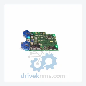
Yaskawa YPHT31033-1-1 73600-A0101 Circuit Board
Yaskawa YPHT31033 Series: Comprehensive Module Range and Technical Overview The Yaskawa YPHT31033 series circuit boards are deployed across heavy industrial…
Model: PCB NO:7337
Product Overview
Commercial availability is handled through direct RFQ, model verification and export-oriented follow-up rather than public cart checkout.
Datasheet Preview
Use attached product manuals when available. If the manual is not public yet, request the full file directly through RFQ.
Commercial Path
Product pages on DRIVEKNMS are designed to verify model, brand and series first, then move the buyer into one clean quotation path.
Technical Dossier
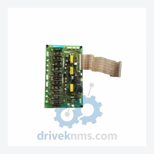
The Thermal Dynamics Pilot PCB Assembly series — anchored by the PCB NO:7337 — represents a core control board lineage deployed across industrial plasma cutting systems used in heavy manufacturing, shipbuilding, structural steel fabrication, and pressure vessel production. Thermal Dynamics, a brand with decades of engineering heritage in arc cutting technology, engineered these pilot PCB assemblies to govern the high-frequency pilot arc ignition sequence, torch enable logic, and fault protection circuitry in its mid-to-high-amperage plasma cutting platforms. These boards are installed in facilities where unplanned downtime carries direct production cost consequences, making reliable spare parts sourcing a critical operational requirement.
The PCB NO:7337 and its sibling assemblies are found in Thermal Dynamics SL-series, Ultra-Cut, and Pak-series plasma cutting systems. Their deployment spans automotive stamping plants, offshore fabrication yards, and contract cutting operations where continuous-duty plasma cutting is standard. As the product line has matured, many of these PCB assemblies have transitioned to end-of-life (EOL) status, making secondary market sourcing and lifecycle extension support the primary procurement channel for maintenance engineers.
Thermal Dynamics' pilot PCB architecture evolved through three distinct generations aligned with the broader development of plasma cutting power supply technology:
Generation 1 (1980s–early 1990s): Discrete component boards using through-hole construction. Pilot arc control was implemented via relay logic and analog timing circuits. These boards are fully obsolete and require component-level repair or cross-reference substitution. Boards from this era include early Pak-10 and Pak-45 platform assemblies.
Generation 2 (mid-1990s–2000s): Transition to mixed through-hole and surface-mount technology (SMT). Introduction of optocoupler isolation between the high-voltage pilot arc circuit and the low-voltage logic control plane. The PCB NO:7337 belongs to this generation, characterized by improved EMI immunity and modular connector interfaces compatible with the SL60/SL100 torch families. Compatibility with earlier torch leads was maintained via adapter harnesses, but backplane pinout differences require verification before substitution.
Generation 3 (2010s–present): Full SMT construction, integrated microcontroller-based fault logging, and CAN bus or serial communication interfaces for integration with CNC cutting tables and height control systems. Modern equivalents such as the Ultra-Cut XT series use proprietary PCB assemblies that are not backward-compatible with Generation 2 platforms without power supply replacement.
For facilities operating Generation 2 Thermal Dynamics systems, the PCB NO:7337 and related assemblies remain the only viable repair path. No drop-in modern replacement exists; the power supply chassis must be retained, making spare board availability the single point of failure for continued operation.
The following SKUs represent verified Thermal Dynamics PCB assemblies and associated control boards used across the Pak, SL, and Ultra-Cut platform families. Each entry reflects a distinct functional role within the plasma cutting system's control architecture.
PCB NO:7337: Pilot arc control PCB assembly; governs HF ignition sequence and torch enable logic for SL-series systems.
PCB NO:7338: Pilot arc timing board variant; extended duty cycle rating for continuous-cut applications.
PCB NO:5765: Main control PCB for Pak-10 plasma system; regulates output current and fault shutdown.
PCB NO:5766: Auxiliary I/O board for Pak-10; interfaces remote start/stop and machine torch signals.
PCB NO:6178: Power factor correction control board used in three-phase Ultra-Cut 100 systems.
PCB NO:6179: Inverter gate drive PCB; controls IGBT switching in Ultra-Cut 150/200 power supplies.
PCB NO:7004: Display and operator interface PCB for SL60/SL100 front panel assembly.
PCB NO:7005: Communication interface board; RS-232 serial output for CNC table integration.
PCB NO:7192: Voltage feedback and regulation PCB; maintains arc voltage stability under variable load.
PCB NO:7193: Current sensing PCB assembly; provides closed-loop current feedback to main controller.
PCB NO:7250: Fault detection and protection PCB; monitors over-temperature, over-current, and gas pressure faults.
PCB NO:7251: Gas control solenoid driver board; manages plasma and shield gas valve sequencing.
PCB NO:7290: HF oscillator PCB; generates high-frequency pilot arc initiation signal for non-contact start torches.
PCB NO:7291: HF suppression and filtering board; reduces conducted EMI from pilot arc circuit to control logic.
PCB NO:7310: Torch body interface PCB; routes coolant flow signals and electrode wear detection for water-cooled torches.
PCB NO:7335: Pre-pilot arc sequencing board; coordinates gas pre-flow timing before HF ignition.
PCB NO:7336: Post-cut gas post-flow control PCB; manages shield gas continuation after arc termination.
PCB NO:7340: Replacement pilot PCB assembly; functionally equivalent to PCB NO:7337 with revised component sourcing for EOL parts.
PCB NO:7410: Power supply regulation PCB for Pak-45 platform; controls output voltage under variable input conditions.
PCB NO:7411: Soft-start and inrush current limiting PCB for Pak-45 three-phase input stage.
The Thermal Dynamics Pilot PCB Assembly series, including PCB NO:7337, is classified as a mature-to-end-of-life product line. Thermal Dynamics (now part of Victor Technologies / ESAB group) has discontinued active production of Generation 2 control boards. OEM new-old-stock (NOS) inventory is exhausted at most authorized distributors, and factory repair services for these assemblies are no longer offered through standard service channels.
DriveKNMS maintains a dedicated inventory program for Thermal Dynamics PCB assemblies sourced through verified industrial surplus channels, decommissioned equipment teardowns, and long-term stocking agreements with regional distributors. Our procurement team actively tracks PCB NO:7337, PCB NO:7338, PCB NO:7340, and related pilot arc boards across global surplus markets.
For facilities requiring lifecycle extension beyond OEM support, DriveKNMS offers: verified used assemblies with full functional test documentation; component-level repair assessment for boards with identifiable failure modes (failed optocouplers, blown gate resistors, capacitor ESR degradation); cross-reference analysis to identify functionally equivalent substitute assemblies where direct replacements are unavailable; and consignment stocking arrangements for high-volume maintenance operations.
Procurement lead times for PCB NO:7337 vary by market availability. Customers are advised to maintain a minimum of two spare assemblies per active plasma cutting system to avoid unplanned downtime during sourcing cycles.
Pilot PCB assemblies present specific test challenges due to the interaction between high-voltage pilot arc circuits and low-voltage logic control planes on a shared board. DriveKNMS applies the following test protocol to all Thermal Dynamics PCB assemblies prior to shipment:
Visual inspection: 10x magnification inspection of all solder joints, component bodies, and PCB traces. Particular attention to HF oscillator section components (capacitors, spark gap assemblies, coupling transformers) and optocoupler isolation barriers, which are the primary failure points in pilot arc boards.
Dielectric isolation test: Hi-pot testing between the high-voltage pilot arc circuit and the low-voltage logic section to verify isolation integrity. Boards failing isolation test are rejected; no repair is performed on isolation-compromised assemblies.
Functional bench test: Each board is installed in a compatible Thermal Dynamics power supply chassis and subjected to a full pilot arc ignition cycle test sequence. Torch enable logic, fault output signals, and timing parameters are verified against OEM specification values.
Burn-in: Boards are operated through a minimum of 50 pilot arc ignition cycles under load to screen for latent component failures before shipment.
Documentation: Each shipped assembly is accompanied by a test record including serial number, test date, technician ID, and pass/fail results for each test stage.
© 2026 DriveKNMS. All trademarks belong to their respective owners. Specifications are for reference only and subject to change without notice. Verify all parameters against official documentation before installation.
Related Paths
Yaskawa YPHT31033 Series: Comprehensive Module Range and Technical Overview The Yaskawa YPHT31033 series circuit boards are deployed across heavy industrial…
YASKAWA YPCT21092-1 Series: Comprehensive Module Range and Technical Overview The YASKAWA YPCT21092-1 series of control boards occupies a critical position…
EPRO PR6426 Series: Comprehensive Module Range and Technical Overview The EPRO PR6426 series is a family of eddy current displacement…