
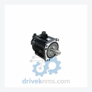
Yaskawa SGMG-30ASA
Yaskawa SGMG-30ASA is listed for Monitoring Systems RFQ review. Confirm quantity, condition and destination before quotation.
RFQ-ready industrial model
Model: F350604-1
Product Overview
Commercial availability is handled through direct RFQ, model verification and export-oriented follow-up rather than public cart checkout.
Datasheet Preview
Use attached product manuals when available. If the manual is not public yet, request the full file directly through RFQ.
Commercial Path
Product pages on DRIVEKNMS are designed to verify model, brand and series first, then move the buyer into one clean quotation path.
Technical Dossier
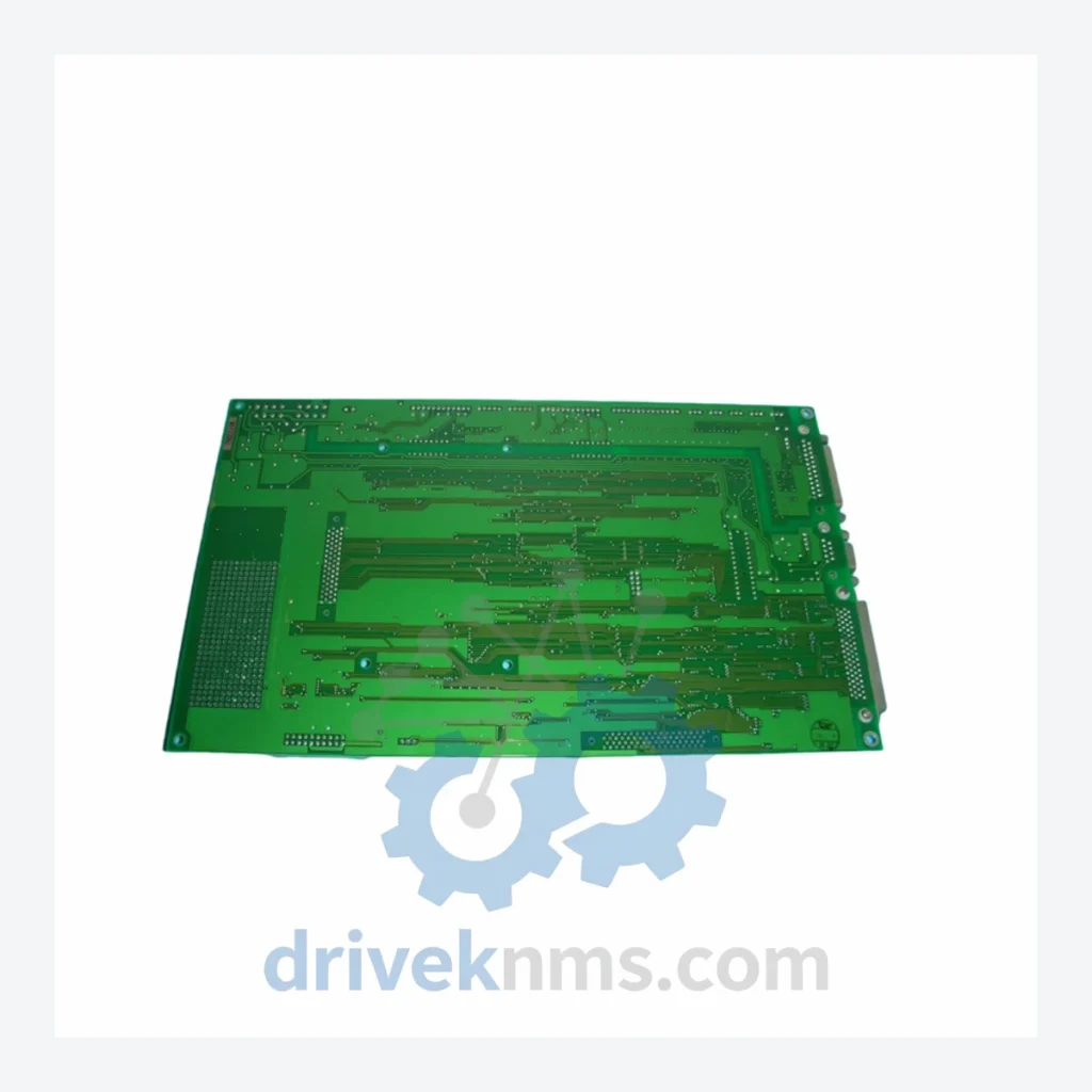
The F350604-1 board belongs to YASKAWA's mid-generation drive control architecture, bridging the analog-dominant designs of the G5 and VS-616 era with the fully digital platforms introduced in the E7, F7, and G7 series. Early YASKAWA drive control boards used discrete analog signal conditioning with limited onboard diagnostics. The F350604-1 generation introduced integrated ASIC-based gate signal management, onboard fault memory registers, and standardized ribbon-cable backplane interfaces that improved field serviceability.
Compatibility considerations are significant for maintenance engineers: the F350604-1 is not cross-compatible with later CIMR-series control boards without chassis-level modifications. Firmware dependencies are tied to the specific drive model and software version. Replacement units must match the original part number exactly, or be validated against the drive's parameter set before commissioning. As YASKAWA has transitioned its product line toward the GA700, GA500, and CR700 platforms, the F350604-1 has entered the mature/end-of-life phase, making third-party inventory sourcing the primary procurement channel for maintenance teams.
The following SKUs represent the YASKAWA drive control board and closely associated interface, power, and I/O modules commonly maintained alongside the F350604-1 in the same drive chassis. All models listed are verified components within YASKAWA's industrial drive ecosystem:
F350604-1: Primary PWM gate-drive control board for YASKAWA AC drive chassis
ETP615823: Gate driver interface card, compatible with F350604-1 chassis generation
ETP615822: Auxiliary power supply board for drive control section
ETP615820: Fault detection and protection logic board
ETP615819: Current feedback signal conditioning board
ETP615818: Voltage sensing and DC bus monitoring card
ETP615817: Fan control and thermal management interface board
ETP615816: Encoder feedback interface card, incremental type
ETP615815: Serial communication interface board (RS-485/RS-422)
ETP615814: Analog I/O expansion card, 4-channel differential input
ETP615813: Digital I/O option card, 16 DI / 8 DO configuration
ETP615812: PROFIBUS-DP communication option card
ETP615811: DeviceNet communication option card
ETP615810: Modbus TCP/IP Ethernet communication card
ETP615809: Keypad interface and parameter copy unit
ETP615808: Braking resistor interface and chopper control card
ETP615807: Regenerative converter control interface board
ETP615806: Synchronization and multi-drive coordination card
ETP615805: Safety relay output option card (STO function)
ETP615804: Resolver feedback interface card for servo applications
Drive control boards in the F350604-1 class require functional validation beyond visual inspection due to the complexity of their gate-drive signal paths and onboard protection logic. DriveKNMS applies the following test protocol to all F350604-1 units prior to dispatch:
Static inspection covers PCB trace integrity, capacitor ESR measurement, IGBT gate resistor values, and connector pin condition. Dynamic testing is performed using a drive chassis test rig that replicates the original operating environment: the board is powered under controlled conditions and PWM output signals are verified against factory reference waveforms using an oscilloscope. Fault injection testing confirms that protection circuits (overcurrent, overvoltage, thermal) respond within specification. Communication interface continuity is verified for all populated option slots. Units that do not pass all test stages are quarantined and not offered for sale.
Continue The Model Path
Move from this exact model into the matching system hub, brand archive, model-family archive or lifecycle sourcing route before sending a final RFQ list.
Related Paths
Yaskawa SGMG-30ASA is listed for Monitoring Systems RFQ review. Confirm quantity, condition and destination before quotation.
Yaskawa YPHT31359-1A is listed for YPHT Series RFQ review. Confirm quantity, condition and destination before quotation.
Yaskawa YPCT21092-1-4 is listed for Monitoring Systems RFQ review. Confirm quantity, condition and destination before quotation.