
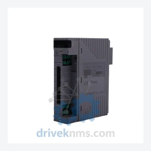
Yokogawa AAI141-S00 Analog Input Module – CENTUM VP S2 Series
Yokogawa AAI141-S00 is listed for CENTUM VP RFQ review. Confirm quantity, condition and destination before quotation.
RFQ-ready industrial model
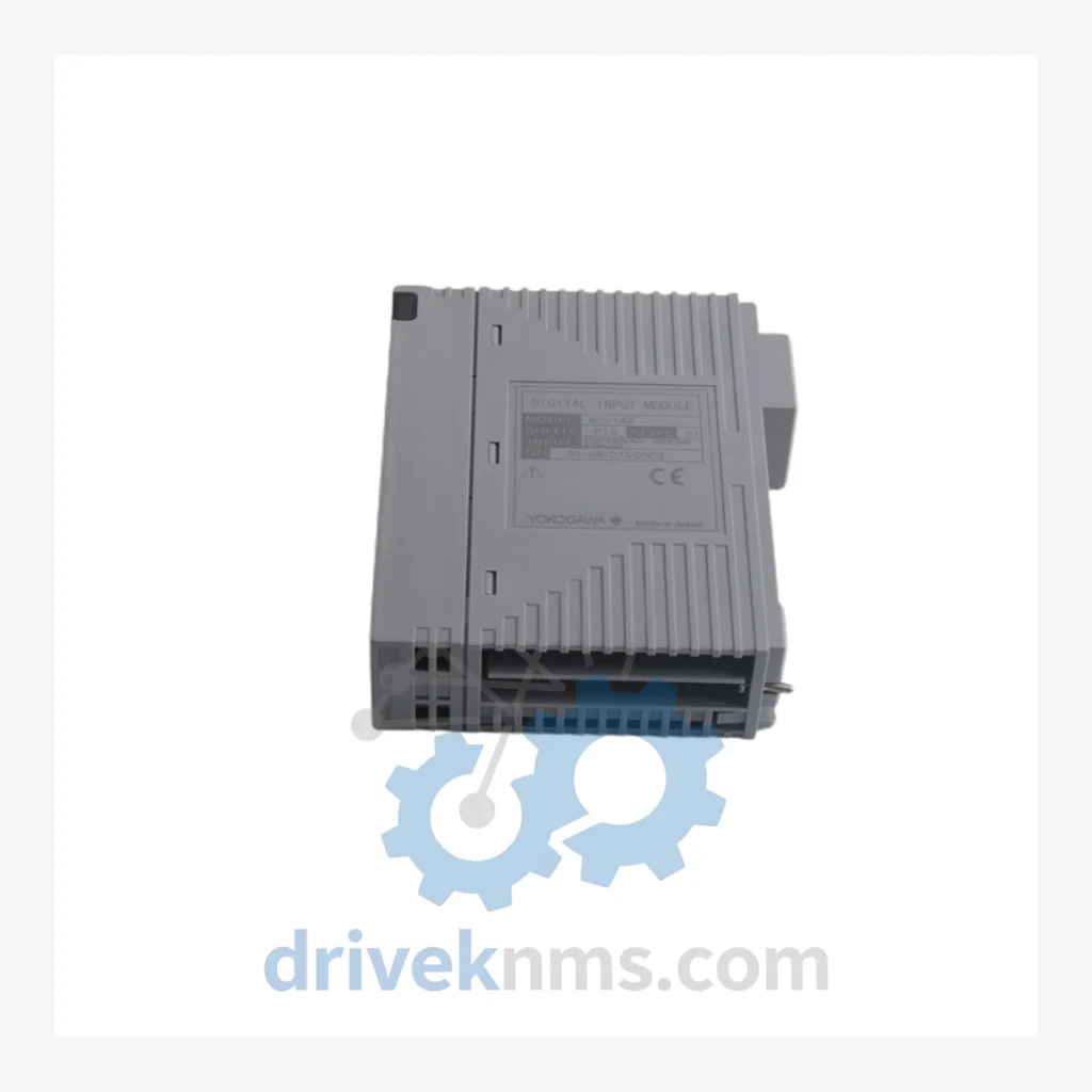
Model: ADV142-P13 S1
Product Overview
Commercial availability is handled through direct RFQ, model verification and export-oriented follow-up rather than public cart checkout.
Datasheet Preview
Use attached product manuals when available. If the manual is not public yet, request the full file directly through RFQ.
Commercial Path
Product pages on DRIVEKNMS are designed to verify model, brand and series first, then move the buyer into one clean quotation path.
Technical Dossier
The ADV142 series traces its lineage to Yokogawa's CENTUM CS 3000 platform, where equivalent DI modules operated under the AAI141/ADV141 designation. When CENTUM VP was introduced in the mid-2000s as the successor architecture, Yokogawa redesigned the I/O subsystem to support higher channel density, improved noise immunity, and compatibility with the Vnet/IP control network. The ADV142 replaced the ADV141 as the standard 32-point DI module, retaining backward-compatible wiring termination to ease migration. Subsequent suffix variants (P00, P10, P13, P50, P53) reflect differences in input voltage range, terminal block configuration, and intrinsic safety certification status. The P13 suffix specifically denotes a 24 VDC input range with a specific terminal block variant suited for marshalling cabinet integration. As CENTUM VP has itself matured into a stable, long-lifecycle platform, the ADV142 series has entered a maintenance phase: Yokogawa continues to supply modules but active development has shifted toward the CENTUM VP R6 and successor I/O architectures. Plants operating legacy CENTUM VP installations must plan for extended spare parts procurement horizons of 10–20 years.
The following SKUs represent the verified ADV142 and closely related ADV-series digital I/O modules within the CENTUM VP I/O subsystem. Each module is a field-replaceable unit (FRU) compatible with standard CENTUM VP node units.
ADV142-P00: 32-point DI module, 24 VDC input, standard terminal block, non-IS.
ADV142-P10: 32-point DI module, 24 VDC input, connector-type terminal, non-IS.
ADV142-P13: 32-point DI module, 24 VDC input, P13 terminal block variant, marshalling-optimized.
ADV142-P50: 32-point DI module, 24 VDC input, intrinsic safety (IS) certified, standard terminal.
ADV142-P53: 32-point DI module, 24 VDC input, IS certified, P53 terminal block variant.
ADV151-P00: 32-point DO module, 24 VDC transistor output, standard terminal, non-IS.
ADV151-P10: 32-point DO module, 24 VDC transistor output, connector terminal, non-IS.
ADV151-P50: 32-point DO module, IS certified, standard terminal block.
ADV149-P00: 16-point DI module, 100/110 VAC input, standard terminal block.
ADV149-P10: 16-point DI module, 100/110 VAC input, connector-type terminal.
ADV551-P00: 32-point DI module, HART-compatible, standard terminal, non-IS.
ADV551-P10: 32-point DI module, HART-compatible, connector terminal, non-IS.
ADV551-P50: 32-point DI module, HART-compatible, IS certified.
ADV557-P00: 16-point DO relay output module, standard terminal block.
ADV557-P10: 16-point DO relay output module, connector-type terminal.
ADV559-P00: 8-point DO relay output module, high-current capacity, standard terminal.
ADV559-P10: 8-point DO relay output module, high-current capacity, connector terminal.
ADV161-P00: 32-point DI module, 48 VDC input range, standard terminal block.
ADV161-P10: 32-point DI module, 48 VDC input range, connector-type terminal.
ADV142-series modules incorporate a multi-layer backplane bus interface that communicates with the CENTUM VP node unit via a proprietary high-speed serial bus. Quality verification for these modules requires purpose-built test procedures beyond standard continuity checks. DriveKNMS applies the following protocol to all ADV142 units prior to dispatch: (1) Visual inspection of PCB, connector pins, and terminal block for mechanical damage, corrosion, or burn marks. (2) Power-on self-test using a CENTUM VP-compatible node unit to verify module recognition and LED status indication. (3) Channel-level functional test: each of the 32 DI channels is individually stimulated with a 24 VDC signal and the corresponding status bit is verified at the FCS level. (4) Isolation resistance test between field-side terminals and system bus to confirm galvanic isolation integrity. (5) Firmware version verification against Yokogawa's published compatibility matrix for the target CENTUM VP release. Modules that fail any stage of this protocol are quarantined and not offered for sale.
Continue The Model Path
Move from this exact model into the matching system hub, brand archive, model-family archive or lifecycle sourcing route before sending a final RFQ list.
Related Paths
Yokogawa AAI141-S00 is listed for CENTUM VP RFQ review. Confirm quantity, condition and destination before quotation.
Yokogawa AAM50 is listed for CENTUM VP RFQ review. Confirm quantity, condition and destination before quotation.
Yokogawa AAM10 is listed for STARDOM RFQ review. Confirm quantity, condition and destination before quotation.