
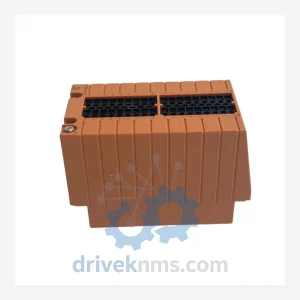
Yokogawa STB4D-10 S2 Digital I/O Terminal Block – Obsolete ProSafe-RS Spare Part
Yokogawa STB4D-10 S2 is listed for ProSafe-RS RFQ review. Confirm quantity, condition and destination before quotation.
RFQ-ready industrial model
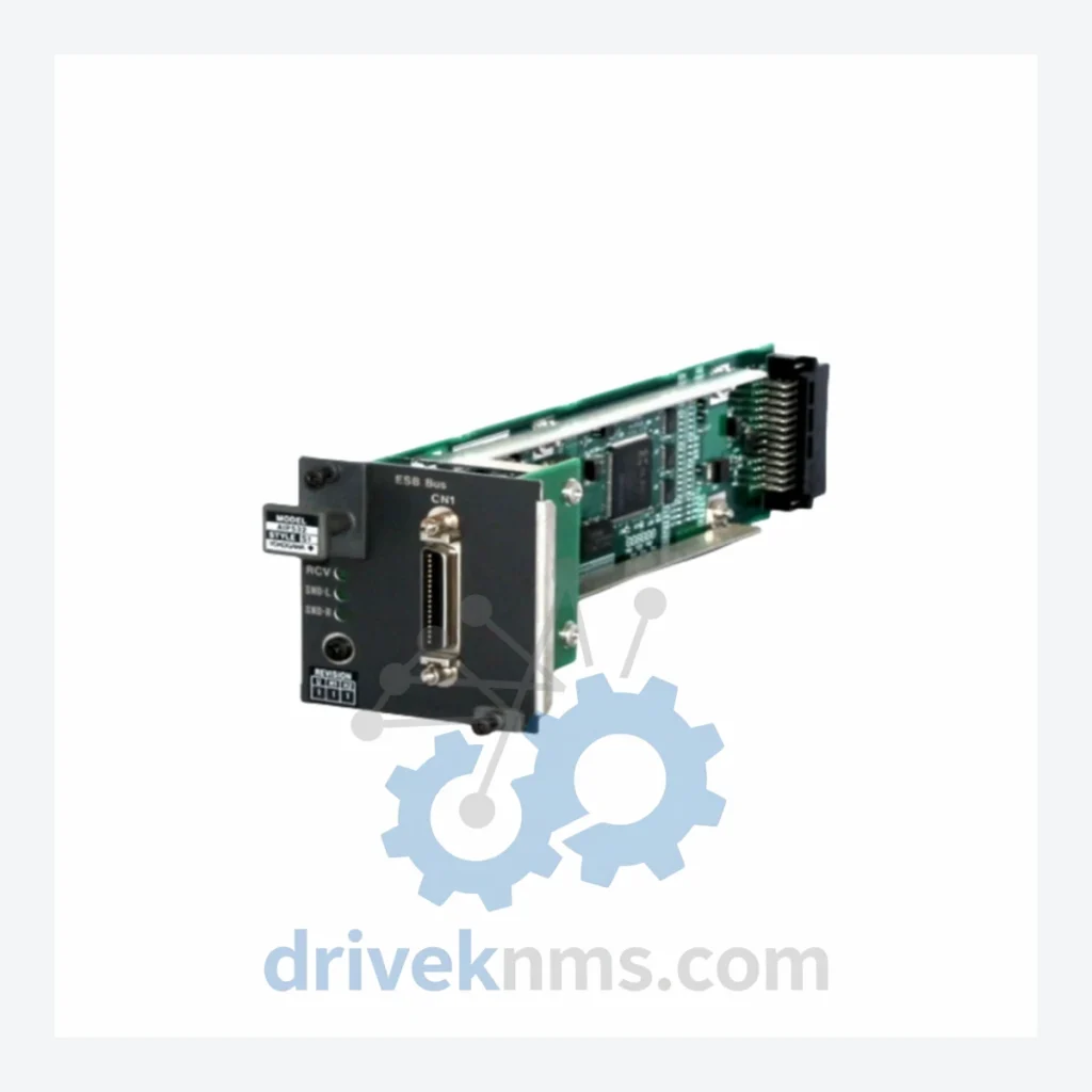
Model: AIP532 S1
Product Overview
Commercial availability is handled through direct RFQ, model verification and export-oriented follow-up rather than public cart checkout.
Datasheet Preview
Use attached product manuals when available. If the manual is not public yet, request the full file directly through RFQ.
Commercial Path
Product pages on DRIVEKNMS are designed to verify model, brand and series first, then move the buyer into one clean quotation path.
Technical Dossier
Yokogawa introduced the ProSafe-RS platform in the early 2000s as a successor to its earlier ProSafe-EX relay-based safety systems. The first-generation ProSafe-RS used a dedicated proprietary bus (ESB – Enhanced Safety Bus) for inter-module communication within the safety controller chassis. The AIP532 ESB Bus Coupler Module belongs to this foundational hardware generation, providing the physical and logical interface between the safety CPU and the analog input sub-modules mounted in the same or adjacent I/O nest.
The following SKUs represent the core ProSafe-RS module catalog. Each entry is classified by functional category. All models listed are confirmed ProSafe-RS platform components.
Safety CPU & Controller Modules
SCP451: Dual-redundant Safety CPU module, SIL 3 rated, Vnet/IP interface, supports up to 2048 I/O points per domain.
SCP461: Enhanced Safety CPU with expanded memory and faster scan cycle for large-scale SIS configurations.
SCM4D-00: Safety Communication Module for Vnet/IP dual-ring integration with CENTUM VP engineering station.
Analog Input Modules
AIP532: ESB Bus Coupler Module; interfaces analog input sub-modules to the ProSafe-RS safety CPU via the Enhanced Safety Bus backplane.
AIP830: 8-channel analog input module, 4–20 mA HART, SIL 2 certified, with per-channel open-circuit and short-circuit diagnostics.
AIP131: 4-channel analog input module for high-accuracy thermocouple and RTD measurement in safety loops.
AIP827: 8-channel analog input, voltage/current selectable, with integrated HART pass-through for field device diagnostics.
AAI143: 16-channel analog input module, 4–20 mA, non-isolated, for high-density I/O nest configurations.
AAI543: 16-channel analog input, isolated, with individual channel fault detection and SIL 2 loop certification.
AAI135: 8-channel analog input, dual-redundant signal path, for 1oo2 voting logic applications.
AAI141: 4-channel analog input, high-impedance voltage input, for pressure transmitter interfaces.
Analog Output Modules
AAP135: 8-channel analog output, 4–20 mA, with readback verification for SIL 2 final element control.
AAP149: 4-channel analog output, isolated, with forced-value override capability for proof-test procedures.
Digital Input / Output Modules
ADV151: 32-channel digital input module, 24 VDC, with per-channel line fault detection for field wiring supervision.
ADV551: 32-channel digital output module, 24 VDC, solid-state, with load current monitoring and short-circuit protection.
SDV541: 16-channel digital output, relay type, for solenoid valve and motor starter interfaces in SIL 2 shutdown loops.
Communication & Bus Modules
ATA4D-00: Termination Assembly for analog I/O modules; provides field wiring marshalling and signal conditioning interface.
ESB10D: ESB Bus Extender Module for expanding the safety I/O nest beyond the base chassis, supporting up to 8 remote I/O nests.
ProSafe-RS modules present specific test challenges due to their dual-channel redundant internal architecture, ESB backplane communication protocol, and self-diagnostic firmware that actively monitors internal signal paths. Standard bench power-up testing is insufficient to validate SIS module integrity.
DriveKNMS applies a structured test protocol for all ProSafe-RS inventory:
1. Backplane Communication Verification: Each module is seated in a live ProSafe-RS test chassis and polled via the ESB bus to confirm correct module ID registration and firmware version reporting.
2. Channel-Level Functional Test: For analog input modules (AIP532, AIP830, AAI543), each channel is stimulated with calibrated 4–20 mA signals at 0%, 25%, 50%, 75%, and 100% of range. Output values are logged against expected engineering unit conversion.
3. Diagnostic Coverage Validation: Internal diagnostic flags (open-circuit, short-circuit, out-of-range) are triggered deliberately on each channel to confirm the module's self-test routines are active and reporting correctly to the safety CPU.
4. Burn-In Cycle: Modules are operated continuously for a minimum of 48 hours at rated voltage and ambient temperature to screen for early-life component failures.
5. Revision Documentation: Hardware revision code, firmware version, and test results are recorded on a per-unit certificate of test, supplied with each module shipped.
Continue The Model Path
Move from this exact model into the matching system hub, brand archive, model-family archive or lifecycle sourcing route before sending a final RFQ list.
Related Paths
Yokogawa STB4D-10 S2 is listed for ProSafe-RS RFQ review. Confirm quantity, condition and destination before quotation.
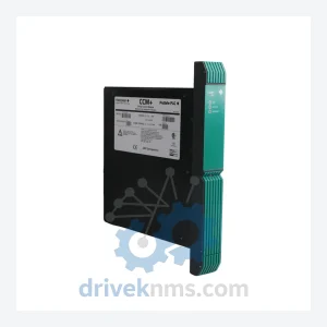
Yokogawa PSCCM24AAN is listed for ProSafe-RS RFQ review. Confirm quantity, condition and destination before quotation.
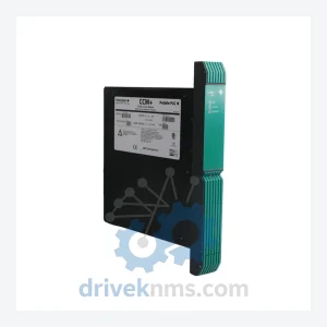
Yokogawa 16418-541/1 PSCCM24AAN is listed for ProSafe-RS RFQ review. Confirm quantity, condition and destination before quotation.