ADVANCED ENERGY 3152225-035A MDX-10K AP1415S 2PW MVE4 RF Generator – 3-Phase 415V
ADVANCED ENERGY 3152225-035A MDX-10K RF Generator: Global Sourcing Strategy & Asset Return Value The ADVANCED ENERGY MDX-10K series (P/N: 3152225-035A,…
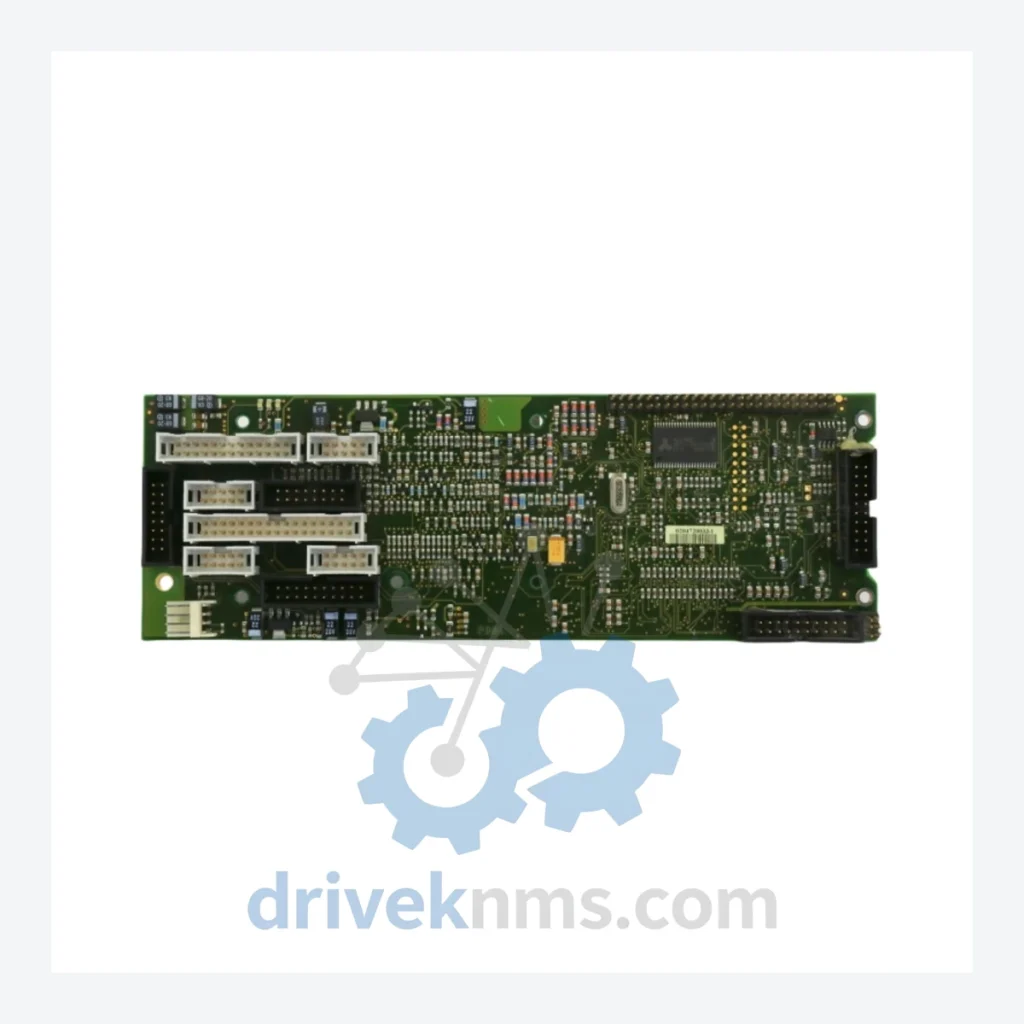
Model: DRE CESAR3-MAIN V2.1 LY210109 DRE C4-MAIN V4.0 LY400268 2305173-A
Product Overview
Commercial availability is handled through direct RFQ, model verification and export-oriented follow-up rather than public cart checkout.
Datasheet Preview
Use attached product manuals when available. If the manual is not public yet, request the full file directly through RFQ.
Commercial Path
Product pages on DRIVEKNMS are designed to verify model, brand and series first, then move the buyer into one clean quotation path.
Technical Dossier
When the main control board of an Advanced Energy CESAR RF power generator fails, the consequences extend far beyond a single component. The CESAR series has been the backbone of RF plasma processes in semiconductor fabrication, flat panel display manufacturing, and industrial thin-film deposition for decades. A single unplanned outage on a production line running this platform can cost a facility tens of thousands of dollars per hour in lost throughput. A forced system upgrade — driven solely by the unavailability of one PCB — routinely demands capital expenditure in the range of several hundred thousand to over one million dollars, factoring in new generator procurement, process requalification, chamber retrofitting, and engineering labor.
DriveKNMS holds verified physical stock of the Advanced Energy DRE CESAR3-MAIN V2.1 (LY210109) and its compatible revision DRE C4-MAIN V4.0 (LY400268 / 2305173-A). For facilities managing aging RF infrastructure, this is not a commodity purchase — it is a risk mitigation decision.
| Parameter | Detail |
|---|---|
| Manufacturer | Advanced Energy Industries, Inc. |
| Part Number (Primary) | DRE CESAR3-MAIN V2.1 / LY210109 |
| Part Number (Compatible) | DRE C4-MAIN V4.0 / LY400268 / 2305173-A |
| Component Type | Main Control PCB Board |
| Platform | Advanced Energy CESAR RF Generator Series |
| Discontinuation Status | Obsolete – No longer manufactured or supported by OEM |
| Country of Origin | United States |
| Condition Available | New Old Stock (NOS) / Professionally Refurbished |
Electrical parameters specific to individual unit configurations are not published here to prevent misapplication. Contact our technical team for configuration verification prior to ordering.
Advanced Energy discontinued active support for the CESAR3 and CESAR C4 generator platforms. Facilities still operating these systems — particularly those running RF plasma processes tied to legacy chamber configurations — face a hard reality: the process recipes, impedance matching networks, and chamber conditioning protocols built around these generators cannot be transferred to a modern replacement without significant requalification effort.
The CESAR3-MAIN and C4-MAIN boards govern the generator's core control logic: power regulation feedback loops, fault detection, interlock management, and communication interfaces to the host process controller. These functions are deeply integrated into the surrounding system architecture. Replacing the generator platform means replacing the entire RF delivery chain — not just the box.
For plant engineers and asset managers operating under capital expenditure constraints, the calculus is straightforward: sourcing a verified replacement PCB at a fraction of the cost of system replacement preserves the existing process baseline, avoids requalification downtime, and extends the productive life of a capital asset that may still have five to ten years of viable service remaining.
Facilities running legacy semiconductor or display fab lines on CESAR-based RF systems should treat this board as a Tier-1 critical spare. A single unit held in bonded inventory eliminates the single point of failure that would otherwise force an unplanned capital decision under production pressure.
The decision to retire a production system is rarely driven by the system's fundamental capability — it is driven by the inability to source replacement components. This is a supply chain problem, not an engineering problem, and it is solvable.
For plant management facing pressure to retire CESAR-based RF infrastructure, the following approach has been applied successfully across semiconductor and industrial coating facilities:
1. Identify the true failure modes. On aging CESAR generators, the most common failure points are the main control board, the RF driver stage, and the power supply section. The main PCB is statistically the highest-risk single point of failure due to electrolytic capacitor aging and firmware dependency.
2. Establish a bonded spare inventory. Procuring one to two verified main control boards and holding them in climate-controlled storage eliminates the lead time risk entirely. The cost of two spare boards is a fraction of one day of unplanned downtime on a production line.
3. Document firmware versions. CESAR main boards carry specific firmware revisions that must match the generator's configuration. Before procurement, verify the firmware version currently installed in your system. DriveKNMS can assist with version identification.
4. Schedule proactive board inspection. Electrolytic capacitors on boards manufactured in the early 2000s are approaching or past their rated service life. A proactive inspection and capacitor refresh — performed during a planned maintenance window — is significantly less disruptive than an emergency replacement during production.
5. Negotiate extended maintenance contracts around verified spare availability. With a confirmed spare parts supply chain in place, facilities can negotiate more favorable terms with their process maintenance contractors, removing the parts unavailability clause that often drives premature system retirement recommendations.
This approach consistently delivers five to ten additional years of productive asset life at a total cost that is one to two orders of magnitude below full system replacement.
DriveKNMS applies a structured 5-step qualification process to all obsolete PCB inventory before shipment:
Step 1 – Electrolytic Capacitor Assessment: All electrolytic capacitors are inspected for physical signs of aging — bulging, electrolyte leakage, and ESR deviation. Boards with capacitors showing measurable degradation are either recapped or quarantined.
Step 2 – Firmware Version Verification: The firmware revision on each board is read and documented. Boards are matched to customer system configurations where version data is available.
Step 3 – Pin and Connector Inspection: All edge connectors, board-to-board connectors, and I/O pins are inspected under magnification for oxidation, corrosion, and mechanical damage. Affected contacts are cleaned or the board is rejected.
Step 4 – Visual PCB Inspection: Trace integrity, solder joint condition, and component seating are verified across the full board surface. Cold joints and lifted pads are documented and addressed.
Step 5 – Functional Bench Test (where applicable): Where test fixtures are available, boards undergo powered functional verification prior to packaging. Test results are documented and available upon request.
All units are packaged in anti-static shielding bags with desiccant and shipped in rigid foam-lined cartons.
Drop-in replacement: The CESAR3-MAIN V2.1 and C4-MAIN V4.0 boards are direct physical and electrical replacements within compatible CESAR generator chassis. No mechanical modification is required for installation.
No reprogramming required: Provided the firmware version matches the existing system configuration, board swap does not require process recipe modification or generator recalibration. This eliminates the need for process engineer involvement in routine board replacement.
Avoids engineering reconstruction costs: Substituting a verified spare board preserves the existing RF delivery system, impedance matching configuration, and process baseline. The alternative — generator replacement — triggers a cascade of engineering costs: new installation, RF cable reconfiguration, match network replacement or retuning, and full process requalification.
Immediate dispatch: Stock is held at DriveKNMS facilities and can be dispatched within 24–48 hours of order confirmation, subject to export documentation requirements.
Q: What warranty applies to obsolete PCB boards?
A: DriveKNMS provides a 90-day warranty against defects in materials and workmanship on all qualified refurbished units. New Old Stock units carry a 180-day warranty. Warranty terms are confirmed in writing at the time of order.
Q: How do I confirm this board is new or professionally refurbished — not field-pulled scrap?
A: Every unit shipped by DriveKNMS is accompanied by a condition report documenting its source classification (NOS or refurbished), the QA steps completed, and the technician sign-off. We do not ship unverified field-pull units without explicit customer acknowledgment and pricing adjustment.
Q: Should I purchase more than one unit?
A: For facilities with multiple CESAR generators or with no alternative RF source for a critical process chamber, holding a minimum of two spare main boards is the standard recommendation. Given the obsolete status of this part, current stock availability cannot be guaranteed beyond the near term. Procurement decisions should be made against current production risk, not future availability assumptions.
Q: Can DriveKNMS assist with installation or firmware verification?
A: DriveKNMS provides pre-shipment technical documentation and can assist with firmware version identification based on your generator serial number. On-site installation support is available through our partner network — contact us to discuss your specific requirements.
Related Paths
ADVANCED ENERGY 3152225-035A MDX-10K RF Generator: Global Sourcing Strategy & Asset Return Value The ADVANCED ENERGY MDX-10K series (P/N: 3152225-035A,…
Advanced Energy APEX Series: Comprehensive Module Range and Technical Overview The Advanced Energy APEX series represents one of the most…
Advanced Energy 2305227-C 0620-01727 0620-02245 Control: Sourcing Strategy & Asset ROI in a Constrained Supply Chain The Advanced Energy 2305227-C…