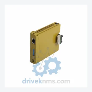
PILZ 773730 PNOZ mc8p Expansion Module – Safety Relay
PILZ 773730 PNOZ mc8p Expansion Module: Global Sourcing Strategy & Asset Return Value The PILZ 773730 PNOZ mc8p is a…
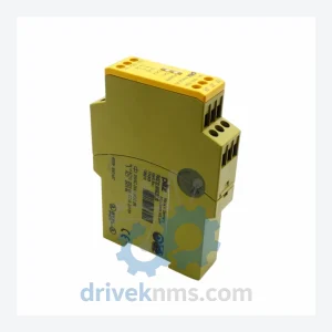
Model: PNOZ X11P
Product Overview
Commercial availability is handled through direct RFQ, model verification and export-oriented follow-up rather than public cart checkout.
Datasheet Preview
Use attached product manuals when available. If the manual is not public yet, request the full file directly through RFQ.
Commercial Path
Product pages on DRIVEKNMS are designed to verify model, brand and series first, then move the buyer into one clean quotation path.
Technical Dossier
The Pilz PNOZ series represents one of the most widely deployed safety relay platforms in global heavy industry. Installed across chemical processing plants, nuclear power facilities, petroleum refineries, offshore platforms, and automotive manufacturing lines, PNOZ modules serve as the backbone of machine safety and emergency stop (E-stop) circuits worldwide. The series complies with EN ISO 13849-1 (up to PL e / Category 4) and IEC 62061 (up to SIL 3), making it the reference standard for functional safety in process-critical environments. The PNOZ X sub-family — which includes the PNOZ X11P — is specifically engineered for monitoring two-hand control circuits, safety gates, and light curtain interfaces with instantaneous and time-delayed output configurations.
The PNOZ product line was introduced by Pilz GmbH & Co. KG (Ostfildern, Germany) in the 1980s as a hardwired, relay-based safety solution. The original PNOZ 1 established the dual-channel monitored input architecture that became the industry template. Through the 1990s, the PNOZ X family expanded to cover diverse input topologies — two-hand control (X11P, X12P), E-stop monitoring (X1, X2, X3), safety mat interfaces (X4), and muting functions (X9).
In the 2000s, Pilz introduced the PNOZmulti configurable safety controller family, enabling logic-based safety functions without discrete wiring. The PNOZmulti 2 (PNOZ m B0, m B1, m EF) followed as the current-generation platform, offering CAN-based expansion and graphical configuration via PNOZmulti Configurator software. For installations still running PNOZ X-series hardware, backward compatibility at the panel wiring level is maintained, but direct module substitution requires engineering review. The PNOZ X series is now in the mature/end-of-active-development phase; Pilz continues to supply spare parts and provides lifecycle extension documentation, but new machine designs are directed toward PNOZmulti 2 or PITreader platforms.
The following SKUs represent verified, commonly stocked modules within the Pilz PNOZ X and PNOZ m product families. Each entry includes a concise functional descriptor for procurement and engineering reference.
PNOZ X1: Single-channel E-stop / safety gate monitor, 24 VDC, 3 NO + 1 NC output contacts.
PNOZ X2: Dual-channel E-stop monitor, 24 VDC/VAC, 3 NO + 1 NC, manual reset.
PNOZ X2.1: Dual-channel E-stop, 24 VDC, 3 NO + 1 NC, auto/manual reset selectable.
PNOZ X2P: Dual-channel E-stop with plug-in terminal base, 24 VDC, 3 NO + 1 NC.
PNOZ X3: Dual-channel E-stop / safety gate, 24 VDC, 4 NO + 2 NC, spring-clamp terminals.
PNOZ X3P: Dual-channel E-stop with plug-in base, 24 VDC, 4 NO + 2 NC outputs.
PNOZ X4: Safety mat / bumper monitor, dual-channel, 24 VDC, 2 NO + 1 NC output.
PNOZ X5: Light curtain / safety gate interface, 24 VDC, 2 NO + 1 NC, OSSD compatible.
PNOZ X6P: Dual-channel E-stop with plug-in base, 24 VDC, 4 NO + 2 NC, Category 4.
PNOZ X7: Dual-channel E-stop / safety gate, 24 VAC/DC, 2 NO + 1 NC, compact housing.
PNOZ X8P: Dual-channel E-stop with plug-in base, 24 VDC, 3 NO + 1 NC, Category 4.
PNOZ X9: Muting relay module, 4-sensor muting, 24 VDC, 2 NO safety outputs.
PNOZ X10: Two-hand control monitor, Type IIIC, 24 VDC, 2 NO + 1 NC, Category 4.
PNOZ X11P: Two-hand control monitor with plug-in base, 24 VDC, 3 NO + 1 NC, Category 4, PL e.
PNOZ X12P: Two-hand control monitor, plug-in base, 24 VDC, 4 NO + 2 NC, Category 4.
PNOZ X13P: Safety gate / E-stop, plug-in base, 24 VDC, 5 NO + 2 NC, Category 4.
PNOZ m B0: PNOZmulti 2 base unit, 8 safe inputs, 2 safe semiconductor outputs, CAN expansion.
PNOZ m B1: PNOZmulti 2 base unit, 20 safe inputs, 4 safe semiconductor outputs, USB config port.
PNOZ m EF: PNOZmulti 2 expansion module, 8 additional safe inputs, plug-in to base unit.
DriveKNMS maintains a dedicated inventory program for Pilz PNOZ X-series modules that have transitioned to limited availability or end-of-production status. For facilities operating legacy safety circuits — particularly those built around PNOZ X1 through X13P variants — unplanned downtime caused by a failed relay module can halt an entire production line or trigger a mandatory safety shutdown under IEC 61511 compliance requirements.
DriveKNMS sources PNOZ X-series stock through authorized distribution channels and verified secondary market suppliers. All units are cross-referenced against Pilz part numbers and date codes prior to acceptance into inventory. For customers requiring long-term maintenance agreements (LTMAs) or buffer stock programs for critical safety infrastructure, DriveKNMS provides multi-unit reservation and scheduled delivery options. Inquiries for obsolete or low-availability PNOZ models — including discontinued variants such as PNOZ 1, PNOZ 5, and early PNOZ X plug-in base configurations — are handled directly by the technical sales team.
Safety relay modules present unique verification challenges compared to standard I/O or power supply components. The PNOZ X11P and related two-hand control modules incorporate force-guided (positive-guided) relay contacts, which must be tested under load to confirm mechanical linkage integrity between NO and NC contact sets — a failure mode not detectable by continuity testing alone.
DriveKNMS applies the following test protocol to all PNOZ X-series units prior to dispatch: (1) Visual inspection of housing, terminal blocks, and LED indicators for physical damage or evidence of prior field modification. (2) Powered functional test at rated supply voltage (24 VDC ±20%) with dual-channel input simulation to verify output switching sequence and reset behavior. (3) Force-guided contact verification: simultaneous measurement of NO and NC contact states under load to confirm positive-guided operation per EN 50205 Class A requirements. (4) Cross-channel monitoring test: deliberate single-channel fault injection to confirm the module correctly inhibits output and requires manual reset. (5) Final continuity and insulation resistance check on all output terminals. Units that do not pass all five stages are quarantined and not offered for sale.
Related Paths
PILZ 773730 PNOZ mc8p Expansion Module: Global Sourcing Strategy & Asset Return Value The PILZ 773730 PNOZ mc8p is a…
Pilz PNOZ X Series: Comprehensive Module Range and Technical Overview The Pilz PNOZ X series represents one of the most…
Pilz PNOZ 11 Safety Gate Monitor – Obsolete PNOZ Series Spare Part When a Pilz PNOZ 11 safety gate monitor…