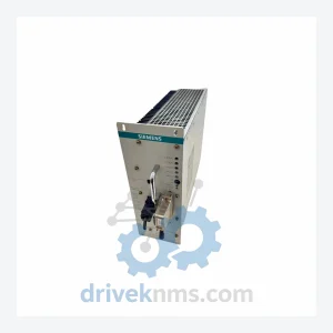
Siemens S31043 Rectifier Modules — S31043-K1166-X
Siemens S31043 Series: Comprehensive Module Range and Technical Overview The Siemens S31043 series comprises rectifier and power supply modules deployed…
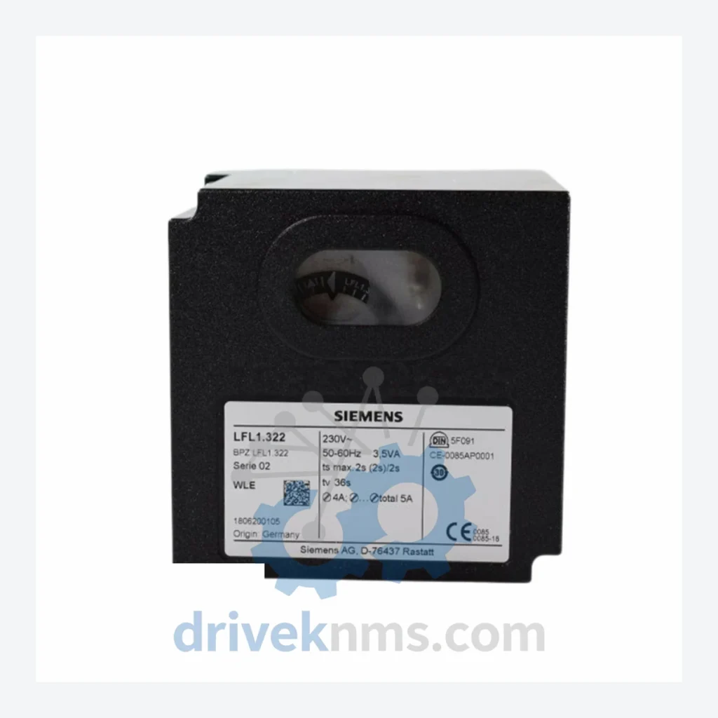
Model: LFL1.322
Product Overview
Commercial availability is handled through direct RFQ, model verification and export-oriented follow-up rather than public cart checkout.
Datasheet Preview
Use attached product manuals when available. If the manual is not public yet, request the full file directly through RFQ.
Commercial Path
Product pages on DRIVEKNMS are designed to verify model, brand and series first, then move the buyer into one clean quotation path.
Technical Dossier
The Siemens LFL1 series of gas burner program controllers occupies a critical position in global heavy industry infrastructure. Deployed across chemical processing plants, nuclear auxiliary systems, petroleum refineries, and district heating stations, the LFL1 family provides sequence-controlled burner management for single-stage and two-stage gas burners. Its relay-based logic architecture, combined with deterministic flame supervision timing, made it the de facto standard for industrial combustion control across Europe, Asia, and the Middle East throughout the 1980s–2010s. Installations remain active in facilities where replacement of the entire burner management system is not economically viable, making long-term spare parts availability a primary operational concern.
The LFL1 series was developed by Siemens Building Technologies (formerly Landis & Gyr, then Landis & Staefa) as a successor to earlier electromechanical burner controllers. The architecture is built around a fixed-program relay sequencer with integrated flame amplifier inputs, designed to accept ionization probes or UV flame detectors. Early variants (LFL1.1xx) operated on 220V AC with fixed lockout timing. Mid-generation models (LFL1.2xx) introduced adjustable pre-purge and safety times via internal DIP switches or potentiometers, improving compatibility with varying combustion chamber volumes. Later variants (LFL1.3xx and LFL1.6xx) extended the series into two-stage burner applications and added compatibility with Siemens QRA2/QRA4 UV detectors and QRB1 infrared detectors.
Compatibility considerations: LFL1 units are not interchangeable with the newer LME/LMO/LMG series (microprocessor-based), which use CAN-bus diagnostics and differ in terminal layout. Facilities migrating from LFL1 to LME71/LME75 require wiring adaptation and recommissioning. For sites that cannot undertake this migration, sourcing original LFL1 units remains the only path to like-for-like replacement.
The following SKUs represent the verified LFL1 series production range. Each unit is a self-contained burner program controller for gas-fired applications.
Single-Stage Controllers (Standard Voltage)
Two-Stage Controllers
Special Voltage / Regional Variants
Siemens has formally discontinued the LFL1 series in favor of the LME/LMO microprocessor-based product line. Official Siemens distribution channels no longer carry LFL1 stock. For facilities operating legacy burner systems — particularly in refineries, chemical plants, and district heating networks where full BMS replacement is deferred — DriveKNMS maintains a dedicated inventory of tested LFL1 units sourced from decommissioned equipment, authorized surplus channels, and verified OEM overstock.
DriveKNMS provides: original-manufacture LFL1 units with full traceability documentation; cross-reference matching between LFL1 variants and equivalent safety-time/voltage specifications; technical consultation on LFL1-to-LME migration feasibility; and emergency same-week dispatch for critical plant shutdowns. All units are individually tested prior to shipment.
The LFL1 series presents specific test requirements due to its relay-based sequencer architecture and integrated flame amplifier circuitry. DriveKNMS applies the following test protocol to every LFL1 unit processed:
Related Paths
Siemens S31043 Series: Comprehensive Module Range and Technical Overview The Siemens S31043 series comprises rectifier and power supply modules deployed…
Siemens ULC Series: Comprehensive Module Range and Technical Overview The Siemens ULC (Unitary Logic Controller) series is a purpose-built line…
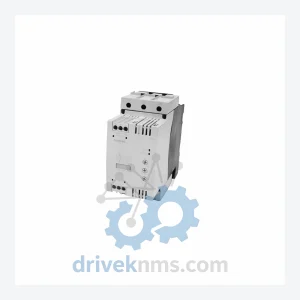
Siemens RW3045-1AB14 Soft Starter: Supply Chain Acquisition Strategy & Asset Return Value The Siemens RW3045-1AB14 is a SIRIUS-series soft starter…