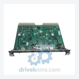
LAM VME LTNI-S5 Power Supply Module – Obsolete VME Series Spare Part
LAM VME LTNI-S5 Power Supply Module – Obsolete VME Series Spare Part When a VME-bus power supply module fails on…
Model: X10-14210100
Product Overview
Commercial availability is handled through direct RFQ, model verification and export-oriented follow-up rather than public cart checkout.
Datasheet Preview
Use attached product manuals when available. If the manual is not public yet, request the full file directly through RFQ.
Commercial Path
Product pages on DRIVEKNMS are designed to verify model, brand and series first, then move the buyer into one clean quotation path.
Technical Dossier
When a power supply module fails inside a LAM Research X10-series process chamber, the consequences extend far beyond a line stoppage. Semiconductor fab managers who have faced this scenario know the calculation: a full tool replacement or platform migration carries capital expenditure in the range of $2–5 million USD, plus 6–18 months of requalification downtime. Against that backdrop, a verified replacement X10-14210100 module is not a spare part — it is a capital asset protection instrument.
DriveKNMS maintains sourced inventory of the X10-14210100 for fabs and equipment owners who cannot afford to treat a discontinued module as a reason to retire a productive tool prematurely.
| Parameter | Detail |
|---|---|
| Part Number | X10-14210100 |
| Manufacturer | LAM Research Corporation |
| Series | X10 |
| Component Type | Power Supply Module |
| Typical Application | LAM Research X10-series etch and CVD process tools |
| Obsolescence Status | Discontinued / End-of-Life (EOL) – no longer manufactured |
| Country of Origin | United States |
| Condition Available | New surplus / Professionally refurbished (see QA section) |
Note: Specific electrical parameters (voltage rails, current ratings, connector pinout) vary by tool configuration. DriveKNMS will provide verified datasheet excerpts upon request. No parameters are published here that cannot be confirmed against original LAM documentation.
LAM Research's X10-series tools were deployed extensively in 200mm and early 300mm fabs during a period when process stability and throughput were the primary engineering priorities. Many of these tools remain in production today — running mature nodes for MEMS, power devices, analog ICs, and compound semiconductors — precisely because the process recipes they run have been qualified over years and are not easily transferred to newer platforms.
The X10-14210100 power supply module sits in the power distribution architecture of these tools. Its failure mode is not gradual degradation visible in process data; it tends to manifest as an abrupt interlock trip or an unrecoverable fault state. At that point, the fab faces a binary choice: source a replacement module or begin the expensive, disruptive process of tool retirement and platform migration.
LAM Research discontinued the X10 series, and OEM support channels for this part number are closed. The secondary market — specifically, suppliers who have invested in locating, testing, and holding verified stock — is the only remaining supply path. Fabs that have not pre-positioned spare modules are entirely dependent on spot availability at the time of failure.
The strategic implication is straightforward: a single X10-14210100 held in bonded stores costs a fraction of one day of unplanned downtime on a productive tool. For fab managers operating under pressure to defer capital expenditure while maintaining output commitments, pre-positioning critical power supply modules is one of the few low-cost, high-certainty risk mitigation measures available.
The decision to retire a process tool is rarely driven by the tool's inability to perform its core function. It is almost always driven by the inability to source a specific failed component. This is the maintenance trap that legacy tool owners must plan around deliberately.
A structured approach to extending X10-series tool life involves three disciplines. First, critical single-point-of-failure modules — power supplies, RF match networks, and chamber control boards — should be identified and a minimum of one spare held on-site or with a verified supplier on allocation. Second, condition monitoring should be applied to power supply modules specifically: periodic measurement of output voltage stability and ripple under load can provide early warning of capacitor degradation before a hard failure occurs. Third, supplier relationships with secondary market specialists should be established before a failure event, not after. Post-failure sourcing under production pressure results in higher prices, unverified parts, and compressed lead times that preclude proper incoming inspection.
Fabs that apply these disciplines consistently report tool operational life extensions of 5–10 years beyond the point at which OEM support was withdrawn. The capital cost of this approach — spare parts, storage, and supplier qualification — is typically recovered within the first avoided downtime event.
DriveKNMS applies a 5-step qualification process to all power supply modules sourced for the secondary market. This process is designed specifically for the failure modes that accumulate in modules that have been in storage or removed from service.
Step 1 – Electrolytic Capacitor Assessment: Electrolytic capacitors are the primary aging component in power supply modules. Each unit is inspected for physical signs of capacitor stress (bulging, electrolyte leakage) and, where test access permits, capacitance and ESR are measured against original specification tolerances.
Step 2 – Firmware and Configuration Verification: Where the module contains programmable elements, firmware version is confirmed against the revision history applicable to X10-series tool configurations. Mismatched firmware versions are a known source of compatibility failures in the field.
Step 3 – Connector and Pin Integrity Inspection: All connector interfaces are inspected under magnification for pin corrosion, fretting damage, and mechanical deformation. Corroded contacts are the second most common cause of intermittent faults in stored modules.
Step 4 – Functional Power-On Test: Modules are powered and output parameters are verified under controlled conditions prior to shipment.
Step 5 – Documentation and Traceability: Each unit is shipped with an inspection record. Lot traceability is maintained for all sourced inventory.
The X10-14210100 is a direct form-fit-function replacement for the original module position in X10-series tools. Installation does not require modification of the tool's electrical architecture, control software, or process recipes. There is no re-programming requirement and no engineering change order process triggered by a like-for-like module swap.
This matters operationally: a maintenance technician familiar with the tool can execute the replacement within a standard planned maintenance window. The alternative — a platform migration — requires process engineers, equipment engineers, and qualification runs that consume productive tool time for months. The cost differential between these two paths is not marginal; it is structural.
For fabs managing a fleet of X10-series tools, DriveKNMS can discuss allocation arrangements that provide priority access to available stock without requiring immediate purchase of the full quantity needed.
Q: What warranty applies to an obsolete part like the X10-14210100?
A: DriveKNMS provides a 90-day warranty covering functional defects identified during incoming inspection or initial installation. Warranty terms for refurbished units are confirmed in writing prior to shipment.
Q: How do I know the unit is genuine and not a counterfeit?
A: All units sourced by DriveKNMS are inspected for manufacturer markings, date codes, and construction consistency with known-good reference units. We do not source from unverified brokers. Traceability documentation is available upon request.
Q: Should I buy more than one unit?
A: For any tool where the X10-14210100 is a single-point-of-failure component and OEM supply is closed, holding a minimum of one spare on-site is a standard risk management practice. For fleets of multiple X10-series tools, the calculus favors holding one spare per two to three tools, depending on tool criticality and acceptable downtime exposure.
Q: What is the lead time?
A: Lead time depends on current stock position. Contact DriveKNMS directly for availability confirmation before committing to a production schedule.
Related Paths
LAM VME LTNI-S5 Power Supply Module – Obsolete VME Series Spare Part When a VME-bus power supply module fails on…
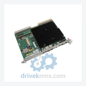
Lam Research VME-7671 Series: Comprehensive Module Range and Technical Overview The Lam Research VME-7671 series represents a core compute and…
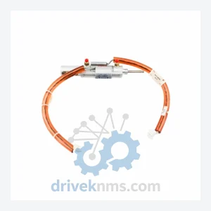
Lam Research 853-031764-001-A Lower Electrode: Supply Continuity Strategy for Semiconductor Fabs The Lam Research 853-031764-001-A (cross-references: A0384140 / A0378622 /…