Technical Dossier
Product Details And Specifications
Baumüller BUS6 Series: Comprehensive Module Range and Technical Overview
The Baumüller BUS6 series represents one of the most widely deployed servo drive and motion control platforms in European heavy industry. Installed across automotive manufacturing lines, paper and printing machinery, plastics extrusion systems, and precision machine tools, the BUS6 architecture has accumulated decades of field deployment in environments where unplanned downtime carries six-figure hourly cost consequences. Facilities running BUS6-based motion control systems — particularly those integrated into multi-axis coordinated drive trains — face a structural challenge: the platform has entered its mature/end-of-life phase, yet the capital cost of full system replacement routinely exceeds the operational budget of a single maintenance cycle. For plant engineering teams, the only financially defensible path is component-level maintenance supported by verified spare parts inventory.
DriveKNMS maintains active stock of BUS6 series modules, including the BUS6-MC-00-S000-3051-SI00-0000 motherboard, sourced through controlled industrial channels and subject to multi-stage functional verification before dispatch.
The Evolution of BUS6 Architecture
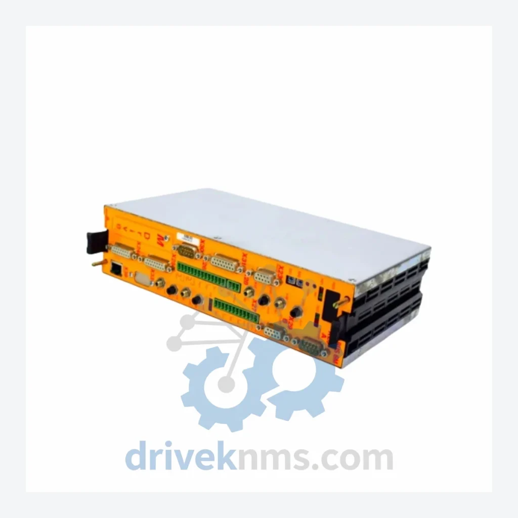
Baumüller introduced the BUS6 platform as a modular, rack-based servo controller architecture designed for synchronous and asynchronous multi-axis motion tasks. The system is built around a central master controller (MC) board — such as the BUS6-MC-00-S000-3051-SI00-0000 — which manages real-time axis coordination, fieldbus communication, and system diagnostics across the backplane bus.
Early BUS6 configurations relied on proprietary Baumüller fieldbus protocols for inter-module communication. Later revisions introduced PROFIBUS-DP and CANopen interface options, expanding integration compatibility with Siemens S7, Beckhoff, and third-party PLC platforms. The transition between firmware generations (particularly the 30xx and 31xx series controller variants) introduced parameter set incompatibilities that require careful version matching during module replacement — a detail that generic spare parts suppliers frequently overlook.
As the BUS6 platform has aged, Baumüller has progressively migrated its active product line toward the b maXX 5000 and b maXX 4000 series. BUS6 is no longer in active production. Replacement modules are available only through secondary market channels, making verified inventory a critical operational resource for facilities that have not yet completed platform migration.
BUS6 Full Catalog & Functionalities (SKU List)
The following SKUs represent confirmed BUS6 series components. Each entry reflects the module's primary functional role within the BUS6 rack architecture:
BUS6-MC-00-S000-3051-SI00-0000: Master controller motherboard; central axis coordination and backplane bus management
BUS6-MC-00-S000-3041-SI00-0000: Master controller variant; earlier firmware revision, 30xx parameter set
BUS6-MC-00-S000-3061-SI00-0000: Master controller variant; extended memory configuration for large axis counts
BUS6-EA-00-S000-0000-SI00-0000: Expansion adapter module; backplane slot extension for additional I/O or drive modules
BUS6-PB-00-S000-0000-SI00-0000: PROFIBUS-DP communication interface module; slave node integration
BUS6-CB-00-S000-0000-SI00-0000: CANopen fieldbus interface module; multi-master network support
BUS6-DI-00-S000-0000-SI00-0000: Digital input module; 24 VDC logic-level signal acquisition
BUS6-DO-00-S000-0000-SI00-0000: Digital output module; relay and transistor output configurations
BUS6-AI-00-S000-0000-SI00-0000: Analog input module; ±10 V / 4–20 mA process signal conditioning
BUS6-AO-00-S000-0000-SI00-0000: Analog output module; setpoint signal generation for external actuators
BUS6-PS-00-S000-0000-SI00-0000: Rack power supply module; 24 VDC backplane power distribution
BUS6-EN-00-S000-0000-SI00-0000: Encoder interface module; incremental and absolute encoder signal processing
BUS6-SY-00-S000-0000-SI00-0000: Synchronization module; multi-rack axis phase locking
BUS6-IO-00-S000-0000-SI00-0000: Combined I/O expansion module; mixed digital signal handling
BUS6-DP-00-S000-0000-SI00-0000: Distributed periphery interface; remote I/O node connectivity
BUS6-CP-00-S000-0000-SI00-0000: Co-processor module; auxiliary computation offload for complex motion profiles
Note: BUS6 part numbers encode configuration options within the string. Confirm full part number against your system's rack label or Baumüller documentation before ordering. DriveKNMS technical staff can assist with cross-referencing.
Sourcing Hard-to-Find & Obsolete BUS6 Parts
With BUS6 no longer in active production, procurement teams face a narrowing window to secure replacement inventory before secondary market supply is exhausted. The BUS6-MC-00-S000-3051-SI00-0000 motherboard is among the highest-demand components in the series, as master controller failures render the entire rack non-operational regardless of the condition of peripheral modules.
DriveKNMS operates a dedicated obsolete parts sourcing function for Baumüller BUS6 inventory. Our procurement network spans decommissioned plant equipment, controlled OEM overstock, and verified industrial surplus channels across Europe and Asia. All units entering our inventory are logged with source documentation and subjected to the QA process described below before being offered for sale.
Quality Control for the BUS6 Range
BUS6 modules — particularly the MC-series motherboards — incorporate complex multi-layer PCB assemblies with dense backplane connector arrays, real-time processor subsystems, and firmware stored on non-volatile memory devices. Standard visual inspection is insufficient for these components. DriveKNMS applies a structured five-stage verification protocol to all BUS6 units:
Stage 1 — Physical Inspection: Full board examination under magnification. Connector pin condition, solder joint integrity, and PCB trace continuity checked. Corrosion, mechanical damage, and evidence of prior repair work documented.
Stage 2 — Electrolytic Capacitor Assessment: All electrolytic capacitors measured for capacitance and ESR. Aged or out-of-tolerance capacitors replaced with rated equivalents before functional testing proceeds.
Stage 3 — Firmware Version Verification: Controller firmware version read and recorded. Compatibility against known BUS6 firmware revision matrix confirmed. Mismatched or corrupted firmware flagged for customer notification prior to shipment.
Stage 4 — Backplane Bus Communication Test: Module installed in a BUS6 test rack and backplane communication integrity verified. Slot addressing, inter-module data exchange, and error flag behavior tested under simulated load conditions.
Stage 5 — Burn-In and Final Functional Test: Module operated under continuous load for a minimum of 4 hours. Thermal performance, output stability, and fault response behavior recorded. Units that pass all five stages are classified as Verified Functional and issued with a test report.
For BUS6 module availability, technical cross-referencing, or volume procurement inquiries: