ALSTOM MVAJ105RA0802A Protection Relay – MiCOM Series
ALSTOM MVAJ105RA0802A Protection Relay: Supply Continuity Strategy for a Discontinued Critical Component The ALSTOM MVAJ105RA0802A is a numerical protection relay…
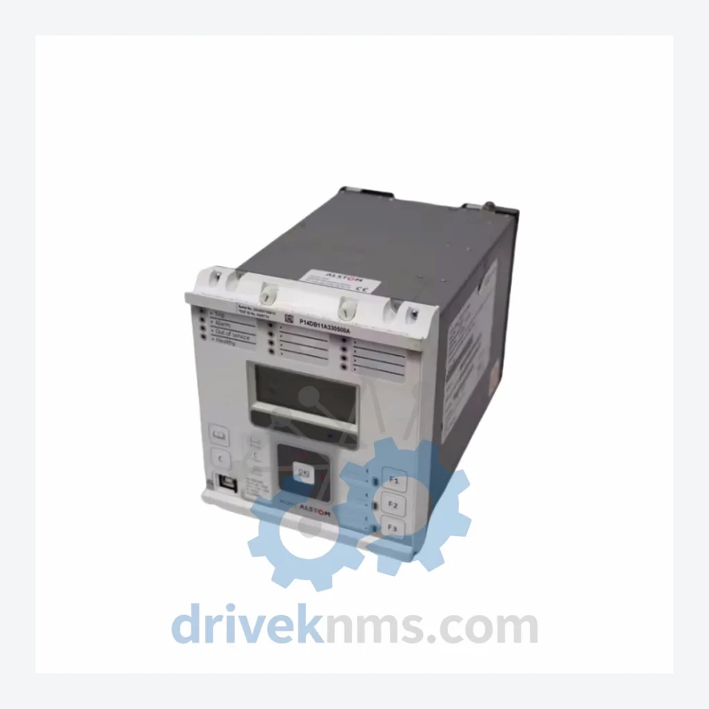
Model: P14DB11A330500A
Product Overview
Commercial availability is handled through direct RFQ, model verification and export-oriented follow-up rather than public cart checkout.
Datasheet Preview
Use attached product manuals when available. If the manual is not public yet, request the full file directly through RFQ.
Commercial Path
Product pages on DRIVEKNMS are designed to verify model, brand and series first, then move the buyer into one clean quotation path.
Technical Dossier
The ALSTOM P14D series is a family of numerical distance protection relays engineered for transmission and sub-transmission line protection in high-voltage grid infrastructure. Deployed across power utilities, petrochemical complexes, nuclear generating stations, and large-scale industrial substations worldwide, the P14D platform occupies a critical position in protection schemes operating at 110 kV to 400 kV. Its IEC 60255-compliant architecture supports zone-1 through zone-5 distance protection, directional earth fault detection, power swing blocking, auto-reclose, and synchrocheck functions within a single chassis. The relay communicates via IEC 61850 GOOSE messaging, DNP3, and Modbus RTU, making it interoperable with modern SCADA and DCS environments. Installed base spans European transmission operators, Middle Eastern grid authorities, and Asian industrial utilities, with documented service lives exceeding 20 years in continuous substation duty.
The P14D series was introduced by ALSTOM Grid (formerly GEC Alsthom, later absorbed into GE Grid Solutions) as a successor to the analogue LFZP and MHOP relay families. First-generation P14D units used a modular card-cage design with separate CPU, I/O, and communication boards interconnected via a proprietary backplane bus. This architecture allowed field replacement of individual function cards without full relay withdrawal, a significant operational advantage in live substation environments.
Second-generation variants introduced a consolidated hardware platform with surface-mount DSP processing, reducing component count and improving MTBF. Communication options expanded from RS-485 Modbus to include IEC 61850 Edition 1 and Edition 2 over Ethernet, enabling integration with IEC 61968/61970 utility enterprise systems. Third-generation firmware releases added enhanced power quality monitoring, synchrophasor (IEEE C37.118) output, and cybersecurity hardening aligned with NERC CIP and IEC 62351 standards.
Compatibility considerations: P14D relays using legacy K-bus or Courier protocol require protocol converters when integrated with IEC 61850 substations. Firmware versions below 0x20 are not compatible with current ALSTOM MiCOM S1 Agile configuration software and require legacy MiCOM S1 Studio v6.x. Hardware variants with suffix codes A, B, and C denote different binary input/output counts and power supply voltage ranges (24–48 V DC, 48–110 V DC, 110–250 V DC).
The following SKUs represent verified models within the ALSTOM P14D protection relay family, classified by functional role and hardware configuration:
Distance Protection Controllers
P14DB11A330500A: 5-zone distance relay, 8BI/8BO, 110–250 V DC supply, IEC 61850 Ed.2, standard I/O configuration for 110–220 kV line protection.
P14DB11A330500B: Identical functional spec to P14DB11A330500A; variant B denotes extended binary output relay contacts rated to 10 A continuous.
P14DB11A330500C: 5-zone distance relay with enhanced power swing detection algorithm; suffix C indicates conformal coating for high-humidity environments.
P14DB21A330500A: Dual-redundant Ethernet port variant; supports HSR/PRP ring topology for IEC 61850 process bus applications.
P14DB31A330500A: Extended I/O version with 16 binary inputs and 16 binary outputs; used in complex busbar protection schemes requiring high contact density.
P14NB11A330500A: Numerical distance relay with integrated line differential protection function; requires fibre-optic or IEEE C37.94 communication channel to remote end.
P14NB21A330500A: Line differential variant with dual redundant communication channels; supports 64 kbps to 2 Mbps channel rates.
P14CB11A330500A: Compact chassis variant for space-constrained panel installations; 4U rack height, reduced I/O count (6BI/6BO).
P14CB21A330500A: Compact chassis with IEC 61850 GOOSE and sampled values (SV) support; designed for digital substation (IEC 61869-9) integration.
P14DB11A220500A: 48–110 V DC power supply variant of the standard P14DB platform; specified for older substation DC systems with lower battery voltage.
P14DB11A110500A: 24–48 V DC power supply variant; used in telecom-standard DC distribution environments and remote switching stations.
P14DB11A330600A: Enhanced distance relay with integrated voltage transformer supervision (VTS) and current transformer supervision (CTS) algorithms.
P14DB11A330700A: Variant with integrated synchrophasor (PMU) output compliant with IEEE C37.118.1-2011; used in wide-area monitoring systems.
P14DB11A330800A: High-impedance fault detection variant; includes sensitive earth fault element for resistive ground fault detection on compensated networks.
P14DB11A330900A: Firmware variant with NERC CIP cybersecurity hardening; includes role-based access control, audit logging, and encrypted Modbus TCP.
P14DB11A331000A: Latest production variant with IEC 62351-8 role-based access control and IEC 61850 Edition 2.1 schema support.
The P14D series has entered the mature-to-declining phase of its product lifecycle. ALSTOM Grid was acquired by GE in 2015, and subsequent rebranding to GE Grid Solutions has resulted in discontinuation notices for several P14D hardware variants. Firmware support for pre-2015 hardware revisions has been formally ended by GE Grid Solutions, and replacement parts through OEM channels are no longer available for suffix-A and suffix-B hardware generations.
DriveKNMS maintains a dedicated inventory of P14D modules sourced from decommissioned substation projects, controlled refurbishment programs, and verified surplus stock channels. All units are catalogued by hardware revision, firmware version, and I/O configuration to ensure exact-match replacement. DriveKNMS provides lifecycle extension support including: original-specification spare boards for CPU, power supply, and I/O card replacement; firmware version matching to avoid configuration incompatibility; and cross-reference services to identify GE Grid Solutions successor models (P40 Agile series) where direct replacement is not feasible. For utilities operating P14D relays under long-term maintenance contracts extending beyond 2030, DriveKNMS offers reserved stock agreements to guarantee parts availability against scheduled maintenance windows.
P14D relays present specific test challenges due to their multi-function protection architecture and backplane-dependent communication between internal modules. DriveKNMS applies the following test protocol to all P14D units processed through its facility:
Power supply verification: DC input range tested at minimum, nominal, and maximum voltage per nameplate specification. Ripple rejection and output regulation measured under full load.
Protection function testing: Each distance zone (Z1–Z5) tested using a three-phase relay test set (Omicron CMC 356 or equivalent) injecting fault voltages and currents at zone boundary impedances. Trip time measured against IEC 60255-121 accuracy class requirements.
Binary I/O functional test: All binary inputs verified for threshold voltage and pickup/dropout timing. All binary output contacts tested for continuity, contact resistance (<100 mΩ), and rated current interruption.
Communication port test: IEC 61850 GOOSE subscription and publication verified using a protocol analyser. Modbus RTU register map validated against factory documentation. Ethernet port tested for 100BASE-TX link integrity and packet error rate.
Backplane bus integrity: Internal communication between CPU, I/O, and communication modules verified by full self-test execution and event log review. Any module reporting CRC errors or bus timeout faults is quarantined for board-level repair.
Final burn-in: Units operated at 40°C ambient for 48 hours under simulated load conditions prior to shipment.
Related Paths
ALSTOM MVAJ105RA0802A Protection Relay: Supply Continuity Strategy for a Discontinued Critical Component The ALSTOM MVAJ105RA0802A is a numerical protection relay…
ALSTOM 7932-4210 Interface Board – Obsolete ALSTOM Spare Part When the ALSTOM 7932-4210 Interface Board fails, the consequences extend far…
ALSTOM 8143 Series: Comprehensive Module Range and Technical Overview The ALSTOM 8143 Series represents a core family of distributed control…