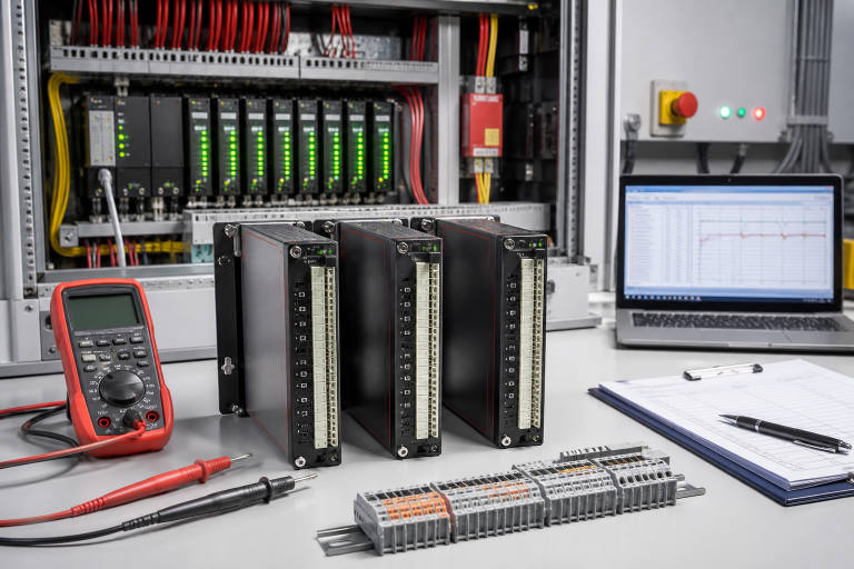
When a protection relay fails or becomes unreadable, the pressure to replace it quickly is real. A breaker may be unavailable, a feeder may be operating under restrictions, and production managers want a clear restoration time. The dangerous shortcut is to treat the replacement as a simple plug-in exercise. Protection depends on settings, CT polarity and ratio, auxiliary supply, trip contacts, interlocks, communications, and the breaker mechanism. A relay that powers up but does not reproduce the approved protection behavior is not a successful repair.
MiCOM-family installations often remain in service long after the original commissioning team has moved on. The most valuable preparation is therefore a compact, controlled record that lets the next engineer identify the exact application and demonstrate the complete trip path. This record also protects procurement from approving a visually similar but electrically different item.
Preserve the as-found state
Before removing a relay, record the full model and order code, hardware and firmware revision, panel location, auxiliary supply, CT and VT ratios, protection elements enabled, setting-file revision, communications address, and output-contact assignments. Photograph the terminals and wire labels from more than one angle. Save event records, disturbance files, active alarms, and the approved settings through the site’s authorized process. If the display is failing, capture whatever information remains before cycling power.
Record the event that led to the replacement request. Was there a genuine fault operation, loss of auxiliary power, a failed self-test, display failure, communications alarm, or an unexplained breaker trip? Note the relay’s event time against the plant clock and compare it with the breaker event recorder or upstream protection. A relay may have operated correctly during a system fault; replacing it without preserving this evidence can erase the explanation.
Prove whether the relay is the failed component
Check auxiliary supply quality and polarity, fuses, terminal connections, earth path, CT shorting links, and trip-coil continuity under the approved switching procedure. A blank display can be caused by a supply problem. A measurement that looks implausible may be a CT secondary issue. A healthy relay output does not prove the breaker opened, and a breaker failure does not automatically mean the relay failed.
Separate the chain into observable points: primary condition, CT/VT input, relay measurement, protection logic, output contact, interposing relay, trip coil, breaker mechanism, and status feedback. Use a qualified protection test set and the plant’s safety rules. Never open a live CT secondary or bypass a trip circuit casually. Record the test method and limits so another engineer can reproduce the result.
Match the spare to the scheme
For an urgent RFQ, send the entire designation, suffixes, current and voltage input requirements, auxiliary supply range, contact configuration, communication option, panel cutout, firmware, quantity, and required delivery date. Include the setting file if it can be shared safely, plus photographs of the rear terminals and nameplate. State the expected condition and require the seller to explain what was tested. “Tested” should identify power-up, input measurement, setting load, output operation, communication, and any functions not covered.
The ALSTOM MVAJ105RA0802A MiCOM-series protection relay is a published catalog item. Its listing is not a declaration that it is interchangeable with every relay in the same family. Compare the exact scheme, input ratings, output mapping, firmware and approved protection philosophy before purchase. A qualified protection engineer should approve the cross-reference and test plan.
Commission the complete trip path
Before energizing, verify the new unit’s identity and condition against the purchase record. Load the approved settings using controlled change management, then compare a setting checksum or export with the authorized file. Check CT polarity and phase assignment, VT inputs where fitted, auxiliary supply, binary inputs, output mapping, alarm routing, time synchronization, and communications. Confirm that protection functions not used by the application remain in the intended state.
Run secondary injection tests for the required elements and record pickup, timing, dropout, and output behavior. Then, under the site’s approved outage and switching plan, prove the relay output through the interposing relay and breaker trip circuit. Verify breaker position feedback, lockout behavior, alarms, SCADA indications, and event capture. Restore temporary test links and blocks with an independent check. Operations should acknowledge the final state before the feeder is returned to service.
Keep the removed relay tagged and preserve its settings and event files until root cause is established. If the replacement solved the symptom, that still does not prove the original unit was the only defect. Compare settings, wiring, supply, and trip circuit results. Update the asset record with serial number, firmware, test results, and the person authorizing the change. This is particularly useful when future maintenance relies on a repaired or tested-used spare.
Questions protection teams ask
Can a MiCOM relay be replaced without re-testing the breaker?
No. The replacement should be tested through its output contacts and the approved trip path, including breaker indication and associated alarms.
Is a relay with the same front label automatically compatible?
No. Check the complete suffix, input ratings, auxiliary supply, contact arrangement, communications, firmware and protection scheme.
What should we request from a spare supplier?
Ask for clear identity photographs, condition disclosure, serial or revision information, documented test scope, warranty terms and dispatch timing.
Why retain the removed relay after the feeder is restored?
It may contain event evidence or reveal a supply, setting, CT or output fault. Keep it until the root-cause review closes.
Restore the protection function, not only the display
A disciplined relay replacement preserves the approved protection behavior while making the outage result auditable. Send DriveKNMS the exact designation, terminal photos, setting context, event evidence, and outage date. We can help confirm the catalog match and quote condition transparently; the site protection authority retains control of settings and acceptance.
© 2026 DriveKNMS. All rights reserved. Official Website: https://driveknms.com Inquiry: sale@driveknms.com | WhatsApp/Tel: +86 18359293191