
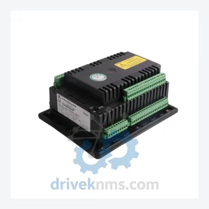
WOODWARD SA1509-24 Solenoid – Governor Control Series
Woodward SA1509-24 is listed for Governor Control Series RFQ review. Confirm quantity, condition and destination before quotation.
RFQ-ready industrial model
Model: 80190-100-01-R
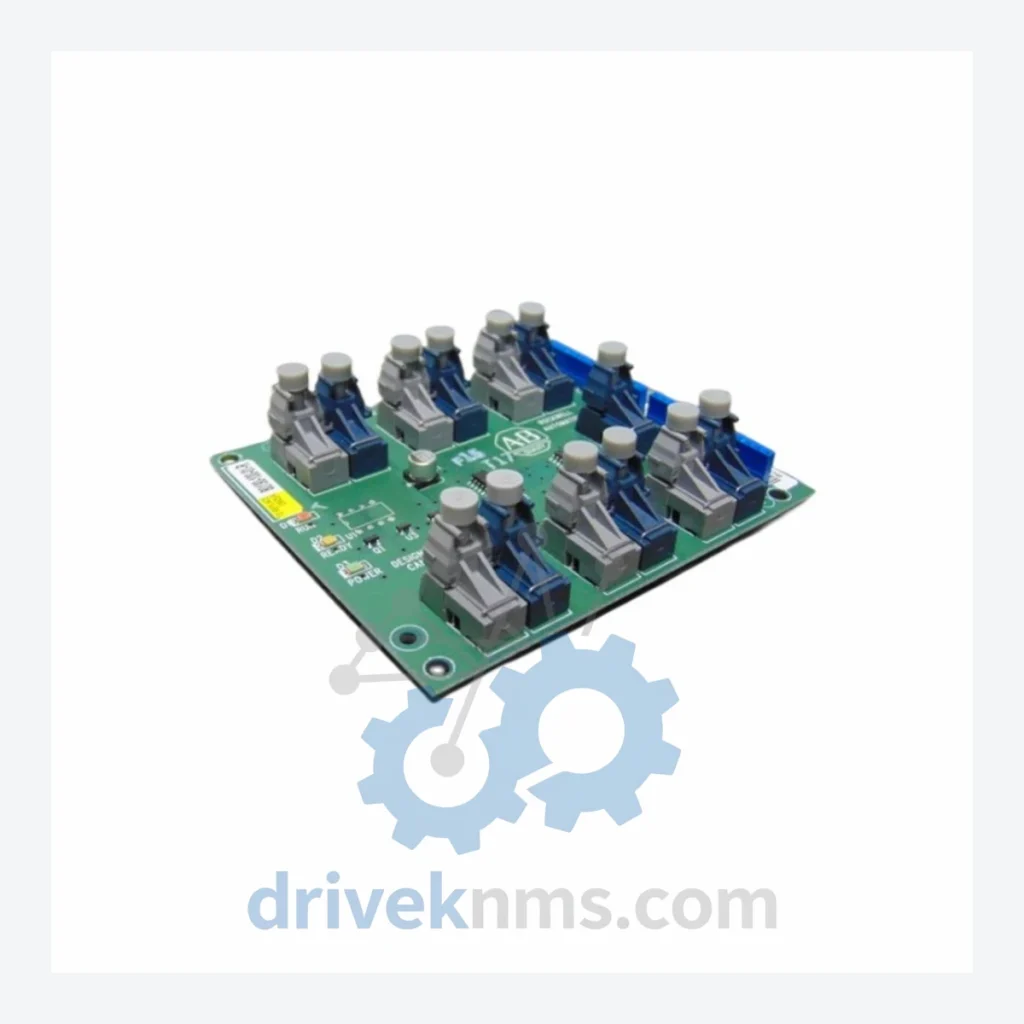
Product Overview
Commercial availability is handled through direct RFQ, model verification and export-oriented follow-up rather than public cart checkout.
Datasheet Preview
Use attached product manuals when available. If the manual is not public yet, request the full file directly through RFQ.
Commercial Path
Product pages on DRIVEKNMS are designed to verify model, brand and series first, then move the buyer into one clean quotation path.
Technical Dossier
The 80190 board family was developed as part of Woodward's modular governor control platform, succeeding earlier discrete relay-based governor panels. Early revisions (suffix -00, -01) established the core backplane communication protocol and analog I/O signal conditioning architecture. The -R suffix designation indicates a revised PCB layout or component substitution to address obsolescence of specific semiconductors, a common lifecycle management practice for long-production-run industrial boards.
Compatibility considerations are critical: the 80190-100-01-R is electrically and mechanically compatible with its predecessor revisions within the same chassis family, but firmware version alignment with the host controller must be verified before substitution. Boards from different sub-series (e.g., 80190-200-xx) may share physical form factor but differ in I/O channel count, communication protocol support, or processor architecture. Field engineers must cross-reference the system's Bill of Materials and the Woodward application manual before installing any revision-level substitute.
The following SKUs represent verified models within the Woodward 80190 control board family, organized by functional category:
Control Processor Boards
Analog I/O Modules
Digital I/O Modules
Communication & Interface Modules
Power Supply Modules
The 80190 control board family incorporates complex backplane bus interfaces and mixed-signal analog circuitry that require specialized test procedures beyond standard power-on verification. DriveKNMS applies the following test protocol to all 80190-series boards prior to shipment:
Continue The Model Path
Move from this exact model into the matching system hub, brand archive, model-family archive or lifecycle sourcing route before sending a final RFQ list.
Related Paths
Woodward SA1509-24 is listed for Governor Control Series RFQ review. Confirm quantity, condition and destination before quotation.
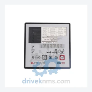
Woodward 8440-1750 EASYGEN-1500-55B is listed for EasyGen-1500 Series RFQ review. Confirm quantity, condition and destination before quotation.
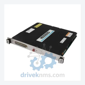
Woodward 5464-544 is listed for Controller Cards RFQ review. Confirm quantity, condition and destination before quotation.