
ABB NTCL01 Communication Termination Unit
ABB NTCL01 is listed for Communication Modules RFQ review. Confirm quantity, condition and destination before quotation.
RFQ-ready industrial model
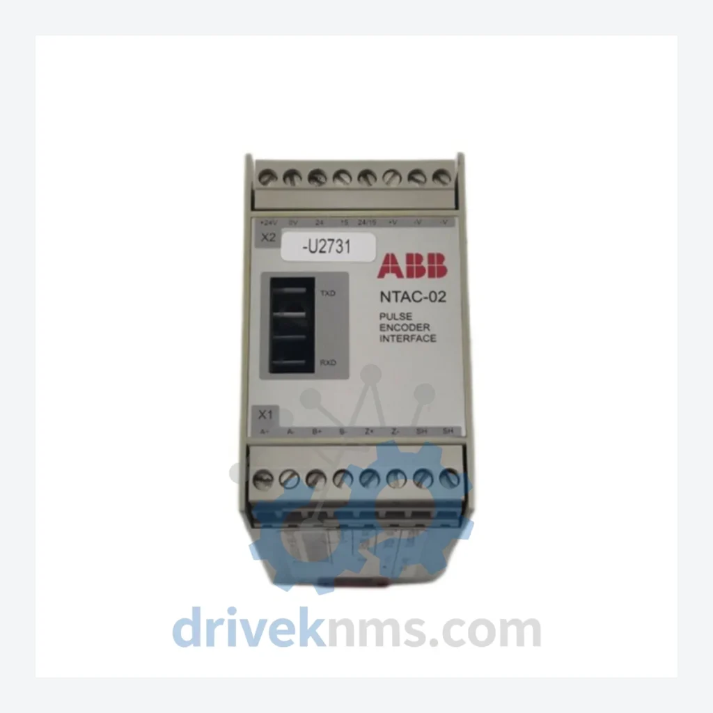
Model: NTAC-02
Product Overview
Commercial availability is handled through direct RFQ, model verification and export-oriented follow-up rather than public cart checkout.
Datasheet Preview
Use attached product manuals when available. If the manual is not public yet, request the full file directly through RFQ.
Commercial Path
Product pages on DRIVEKNMS are designed to verify model, brand and series first, then move the buyer into one clean quotation path.
Technical Dossier
The ABB NTAC series of pulse encoder interface modules occupies a critical position in heavy industrial drive systems globally. Deployed across chemical processing plants, nuclear power facilities, oil refineries, and steel mills, NTAC modules serve as the precision feedback link between incremental encoders and ABB's ACS and DCS series variable frequency drives. Their role in closed-loop speed and position control makes them indispensable for processes where speed accuracy tolerances are measured in fractions of a percent. The NTAC-02, as the primary variant in this series, is compatible with ABB's RDCO, RMIO, and RINT option board ecosystems, and interfaces directly with the drive's DDCS fiber-optic communication channel. Installed base figures across Europe, Asia-Pacific, and the Americas number in the tens of thousands of units, with many installations dating back to the mid-1990s ACS 600 and ACS 800 platform rollouts.
The NTAC series was introduced by ABB as part of the modular option board strategy for the ACS 600 platform, which entered production in the early 1990s. At that time, encoder feedback was handled by discrete wiring to drive control boards, creating noise susceptibility and limiting cable run distances. The NTAC module standardized this interface by providing differential line receiver inputs (RS-422 compatible), onboard signal conditioning, and a standardized slot-mount form factor for ABB's option board bays.
Compatibility matrix summary: NTAC-02 is confirmed compatible with ACS 600, ACS 800, and select ACS 1000 configurations. It is not natively compatible with ACS 880 ZCU control units without hardware adaptation.
The following SKUs represent the verified NTAC series and closely associated ABB encoder/feedback interface modules used within the same drive platform ecosystem. Each entry reflects a distinct hardware variant with specific electrical or mechanical characteristics.
NTAC-02: Pulse encoder interface, single-channel, RS-422 differential input, DDCS fiber output, for ACS 600/800.
NTAC-01: Earlier single-channel encoder interface variant; predecessor to NTAC-02, limited ACS 600 compatibility only.
NTAC-03: Dual-channel encoder interface supporting master-follower speed synchronization configurations.
MTAC-01: Next-generation encoder interface for ACS 880 ZCU control units; direct functional successor to NTAC-02.
RTAC-01: Resolver-to-digital interface module; used where resolver feedback replaces incremental encoders.
RTAC-02: Enhanced resolver interface with extended resolver excitation frequency range.
FTAC-01: Frequency-to-analog tachometer interface for legacy tachogenerator feedback signals.
OTAC-01: Optical encoder interface for high-resolution absolute encoder feedback (SSI protocol).
NAIO-03: Analog I/O extension module used alongside NTAC in multi-feedback configurations.
RDCO-01: DDCS fiber-optic communication adapter; required host board for NTAC-02 in ACS 600.
RDCO-02: DDCS fiber-optic adapter, extended channel version for multi-drive DDCS ring topologies.
RDCO-03: DDCS adapter with enhanced noise immunity for high-EMI industrial environments.
RMIO-01: Main control board for ACS 800; primary host for NTAC-02 option slot installation.
RMIO-02: Revised ACS 800 control board with expanded I/O; compatible NTAC-02 host.
RINT-5311C: Rectifier interface board used in ACS 800 multi-drive configurations alongside NTAC feedback.
RINT-5514C: Inverter interface board; paired with NTAC-02 in ACS 800 common DC bus systems.
NAMC-03: Application control module for ACS 800; coordinates NTAC-02 feedback data in motion control applications.
NAMC-11: Advanced application module supporting adaptive programming with NTAC encoder feedback loops.
DriveKNMS maintains a dedicated inventory of NTAC-02 and associated NTAC series modules sourced from decommissioned equipment, controlled factory surplus, and verified refurbishment programs. All units are catalogued by firmware revision and hardware revision code where applicable. DriveKNMS provides lifecycle extension support specifically for end-of-life ABB drive modules, including cross-referencing obsolete part numbers to current replacement options and advising on NTAC-02 to MTAC-01 migration paths where hardware upgrades are feasible.
NTAC-02 modules present specific test challenges due to their role as a signal-conditioning and protocol-conversion device. Standard power-on tests are insufficient to validate encoder interface integrity. DriveKNMS applies a multi-stage verification protocol to all NTAC units prior to dispatch:
Stage 1 — Visual and Physical Inspection: Examination of the DDCS fiber-optic transceiver for lens contamination or physical damage. Inspection of the RS-422 differential input terminal block for pin corrosion or mechanical deformation. Verification of the option board connector pins against ABB's published pin-out specification.
Stage 2 — Powered Functional Test: Module is installed in a test rig replicating the ACS 800 RMIO option slot environment. A calibrated incremental encoder signal generator (A/B/Z channel, selectable PPR from 256 to 4096) is applied to the RS-422 inputs. DDCS output is monitored via fiber-optic analyzer to confirm correct speed word transmission at multiple test frequencies.
Stage 3 — Communication Protocol Validation: DDCS data frames are decoded and verified against ABB's DDCS protocol specification to confirm correct channel ID assignment, data word formatting, and error flag behavior under simulated signal fault conditions (open channel, signal inversion).
Stage 4 — Thermal Cycling: Units are subjected to a thermal cycle between 0°C and 55°C operating range to identify latent solder joint failures or component drift that would not appear under static test conditions.
Continue The Model Path
Move from this exact model into the matching system hub, brand archive, model-family archive or lifecycle sourcing route before sending a final RFQ list.
Related Paths
ABB NTCL01 is listed for Communication Modules RFQ review. Confirm quantity, condition and destination before quotation.
ABB NINT-73C is listed for Communication Modules RFQ review. Confirm quantity, condition and destination before quotation.
ABB SDCS-IOB-1 3BSE004084R1 is listed for Communication Modules RFQ review. Confirm quantity, condition and destination before quotation.