Technical Dossier
Product Details And Specifications
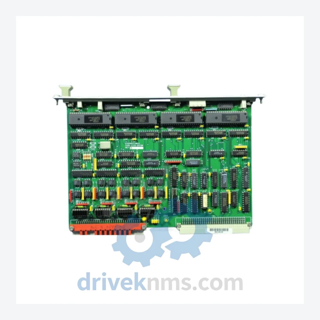
Applied Materials 2711-T10C1X PCB Stepper Drive – Obsolete Spare Part for Semiconductor Equipment
Solving the Discontinued Hardware Crisis
Applied Materials' legacy semiconductor equipment platforms — including older CVD, PVD, and etch systems — were engineered around modular PCB-based motion control. The stepper drive board governs precise wafer handling and chamber positioning. Without it, the entire process module is inoperable.
The 2711-T10C1X assembly integrates Allen-Bradley PanelView-series control logic with a dedicated stepper drive stage. Allen-Bradley formally discontinued the 2711-T series, and Applied Materials no longer supplies this board through standard service channels. Facilities running these tools face a hard choice: locate a verified spare, or commit to a platform migration that disrupts production schedules for months.
How to extend your Applied Materials equipment life by 5–10 years through targeted spare parts management:
Condition & Reliability Assurance
Every 2711-T10C1X / 0100-00003 PCB Stepper Drive unit shipped by DriveKNMS passes a five-stage quality process before dispatch:
- Visual Inspection: Full board examination under magnification for mechanical damage, solder joint integrity, and component seating. Pin and connector corrosion is assessed and documented.
- Electrolytic Capacitor Assessment: Capacitors are tested for ESR (Equivalent Series Resistance) and capacitance drift. Units showing degradation beyond tolerance are recapped with equivalent-specification components.
- Firmware Version Verification: Where firmware is embedded, the revision is read and recorded. Customers are notified of the exact firmware version prior to shipment to confirm compatibility with their host system.
- Pin and Connector Integrity Check: All edge connectors and pin headers are cleaned, inspected for oxidation, and tested for continuity. Corroded contacts are treated or the unit is rejected.
- Functional Burn-In Test: Units are powered and exercised under controlled conditions to confirm baseline operational status before packaging.
Key Features for System Maintenance
Q: How do I confirm the unit is genuine and not a remarked counterfeit?
A: We provide full photographic documentation of board markings, date codes, and serial numbers prior to shipment. Customers may request a pre-shipment inspection report. We do not source from unverified brokers.
Q: Should I buy more than one unit?
A: For any tool running in production, yes. This part is no longer manufactured. Once current market inventory is exhausted, no further supply will exist. Facilities with multiple tools of the same type should consider purchasing one spare per active tool as a minimum position.