B&R IF681 Modules | 3IF681.86
B&R IF681 Series: Comprehensive Module Range and Technical Overview The B&R IF681 series is a line of interface modules developed…
Model: 7DM465.7
Product Overview
Commercial availability is handled through direct RFQ, model verification and export-oriented follow-up rather than public cart checkout.
Datasheet Preview
Use attached product manuals when available. If the manual is not public yet, request the full file directly through RFQ.
Commercial Path
Product pages on DRIVEKNMS are designed to verify model, brand and series first, then move the buyer into one clean quotation path.
Technical Dossier
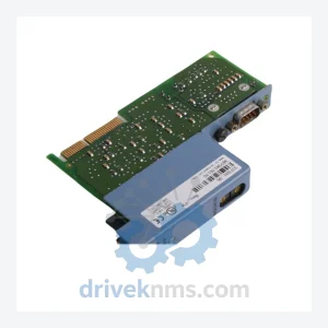
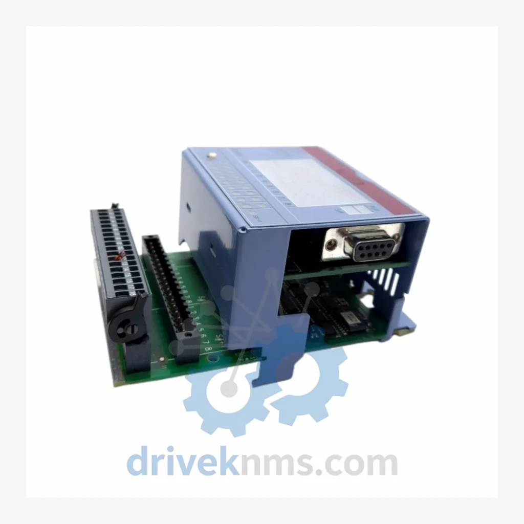
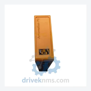
The B&R 7DM series represents a generation of digital input/output modules deployed extensively across heavy industrial sectors including petrochemical plants, nuclear power facilities, oil refineries, and continuous-process manufacturing lines. Manufactured in Austria by Bernecker + Rainer Industrie-Elektronik GmbH (B&R), these modules integrate into the B&R 2003, 2005, and Automation PC/PLC backplane architectures. Their 24 VDC digital I/O architecture, deterministic scan cycle behavior, and DIN-rail form factor made them a standard specification in distributed control system (DCS) and programmable logic controller (PLC) panels throughout the 1990s and 2000s. Installed base counts in the tens of thousands of nodes globally, meaning lifecycle support and spare parts availability remain operationally critical for plant engineers managing aging infrastructure.
The 7DM series was introduced as part of B&R's second-generation modular I/O platform, designed to interface with the B&R 2003 system bus. Early variants used parallel backplane communication with fixed address DIP-switch configuration. Mid-generation revisions introduced improved noise immunity ratings (EN 61000-4 compliance) and extended operating temperature ranges to accommodate outdoor enclosure installations. Later variants within the 7DM family adopted optocoupler-isolated inputs as standard, replacing earlier transistor-coupled designs to meet IEC 61131-2 Type 1/Type 3 input specifications.
Compatibility across sub-generations is not universal. Modules with hardware revision index below .4 may not be pin-compatible with backplanes manufactured after 1998 without adapter brackets. Engineers sourcing replacement units must verify the hardware revision suffix (e.g., .7 in 7DM465.7) against the original system documentation. B&R's successor platforms — the X20 and X67 series — are not backward-compatible with 7DM backplane slots and require full rack replacement if upgrading.
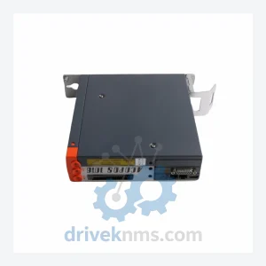
The following SKUs represent verified, commonly deployed modules within the B&R 7DM series. Each entry reflects a distinct hardware configuration. Functional categories: DI = Digital Input, DO = Digital Output, DIO = Digital Input/Output (mixed), PWR = Power Supply Module, CPU = Controller/Processor Module, COM = Communication Adapter.
B&R officially discontinued active production of the 7DM series. Replacement with current-generation X20 or X67 modules requires hardware redesign and is not a drop-in substitution. For facilities operating under long-term maintenance contracts, capital expenditure constraints, or regulatory freeze requirements (common in nuclear and pharmaceutical environments), sourcing original 7DM hardware is the only viable path to maintaining system integrity.
DriveKNMS maintains a dedicated inventory of tested 7DM series modules sourced from decommissioned systems, authorized surplus channels, and controlled factory stock. All units are cataloged by part number and hardware revision index. Customers requiring specific revision levels (e.g., .7 vs .6) for backplane compatibility can specify requirements at the time of inquiry. Long-term supply agreements and consignment stock arrangements are available for facilities with recurring 7DM demand.
The 7DM series uses a parallel backplane bus with multiplexed address/data lines. Failure modes specific to this architecture include bus contention from faulty address latches, degraded optocoupler response time causing input timing errors, and relay contact wear on output modules. DriveKNMS applies a structured test protocol to all 7DM units prior to dispatch:
Modules that fail any test parameter are quarantined, documented, and not offered for sale. Test records are available upon request for quality-critical procurement processes.
Related Paths
B&R IF681 Series: Comprehensive Module Range and Technical Overview The B&R IF681 series is a line of interface modules developed…
B&R 5V3A0100000040-000 Programmable Logic Controller – Obsolete Legacy Spare Part When a B&R 5V3A0100000040-000 PLC module fails on an active…
B&R ACOPOS Series: Comprehensive Module Range and Technical Overview The B&R ACOPOS servo drive series is one of the most…