
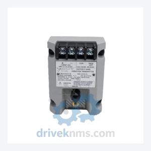
Bently Nevada 990 Series Modules - 990-04-XX-02-05 MOD:167577-05
Bently Nevada 990-04-XX-02-05 MOD:167577-05 is listed for 990 Series RFQ review. Confirm quantity, condition and destination before quotation.
RFQ-ready industrial model
Model: 990-05-XX-01-00 MOD: 167577-07
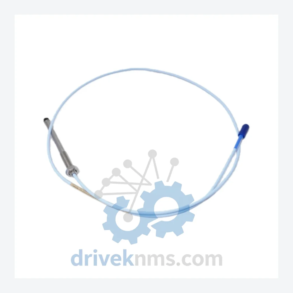
Product Overview
Commercial availability is handled through direct RFQ, model verification and export-oriented follow-up rather than public cart checkout.
Datasheet Preview
Use attached product manuals when available. If the manual is not public yet, request the full file directly through RFQ.
Commercial Path
Product pages on DRIVEKNMS are designed to verify model, brand and series first, then move the buyer into one clean quotation path.
Technical Dossier
The Bently Nevada 990 Series is a dedicated line of vibration monitoring and machinery protection transmitters engineered for continuous deployment in heavy industrial environments. Installed across global petrochemical complexes, nuclear power stations, offshore platforms, and refinery rotating equipment trains, the 990 Series occupies a critical position in plant-wide condition monitoring architectures. Its primary function is the conversion of raw transducer signals—from proximity probes, accelerometers, and velocity sensors—into standardized 4–20 mA analog outputs compatible with DCS, PLC, and SCADA systems. The series is fully interoperable with Bently Nevada's 3300, 3500, and System 1 monitoring platforms, making it a standard specification item in long-term asset integrity programs at facilities operated by ExxonMobil, Shell, SABIC, and comparable tier-1 operators.
The 990 Series was introduced as a field-mount alternative to rack-based monitoring systems, addressing the need for distributed vibration measurement without centralized monitor infrastructure. Early variants such as the 990-05-XX-01-00 established the core signal conditioning architecture: a two-wire loop-powered transmitter accepting input from eddy-current proximity probes and outputting a proportional 4–20 mA signal representing gap, vibration amplitude (peak-to-peak), or both, depending on configuration via the MOD suffix.
The MOD designation (e.g., MOD: 167577-07) encodes factory-configured options including measurement range, output scaling, alarm relay configuration, and transducer compatibility. This modular configuration approach allowed the 990 Series to serve across radial vibration, axial position, and differential expansion measurement applications without hardware redesign. Over successive revisions, Bently Nevada introduced enhanced EMI shielding, extended temperature ratings (–40°C to +85°C), and ATEX/IECEx hazardous area certifications for Zone 1 and Zone 2 installations.
As the broader Bently Nevada portfolio transitioned toward the 3500 Series rack-based system and later the System 1 software platform, the 990 Series entered a mature/end-of-life phase for new installations. However, the installed base remains substantial. Facilities with legacy 990 Series deployments require ongoing spare parts support for planned maintenance intervals, unplanned failures, and instrument calibration cycles. DriveKNMS maintains dedicated inventory and sourcing channels for the full 990 Series range to support these lifecycle requirements.
The following SKUs represent verified, commonly sourced models within the Bently Nevada 990 Series. Models are classified by primary measurement function:
Radial Vibration Transmitters
Axial Position Transmitters
Differential Expansion / Case Expansion Transmitters
Velocity / Seismic Transmitters
The 990 Series transmitter architecture presents specific test requirements due to its proximity probe signal conditioning circuitry and 4–20 mA loop integrity dependencies. DriveKNMS applies the following verification protocol to all 990 Series units prior to shipment:
Continue The Model Path
Move from this exact model into the matching system hub, brand archive, model-family archive or lifecycle sourcing route before sending a final RFQ list.
Related Paths
Bently Nevada 990-04-XX-02-05 MOD:167577-05 is listed for 990 Series RFQ review. Confirm quantity, condition and destination before quotation.
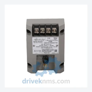
Bently Nevada 990-10-50-01-01 is listed for 990 Series RFQ review. Confirm quantity, condition and destination before quotation.
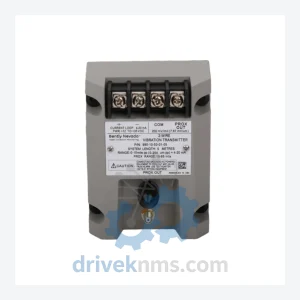
Bently Nevada 990-05-70-01-CN is listed for 990 Series RFQ review. Confirm quantity, condition and destination before quotation.