B&R IF681 Modules | 3IF681.86
B&R IF681 Series: Comprehensive Module Range and Technical Overview The B&R IF681 series is a line of interface modules developed…
Model: 8V1016.50-2
Product Overview
Commercial availability is handled through direct RFQ, model verification and export-oriented follow-up rather than public cart checkout.
Datasheet Preview
Use attached product manuals when available. If the manual is not public yet, request the full file directly through RFQ.
Commercial Path
Product pages on DRIVEKNMS are designed to verify model, brand and series first, then move the buyer into one clean quotation path.
Technical Dossier
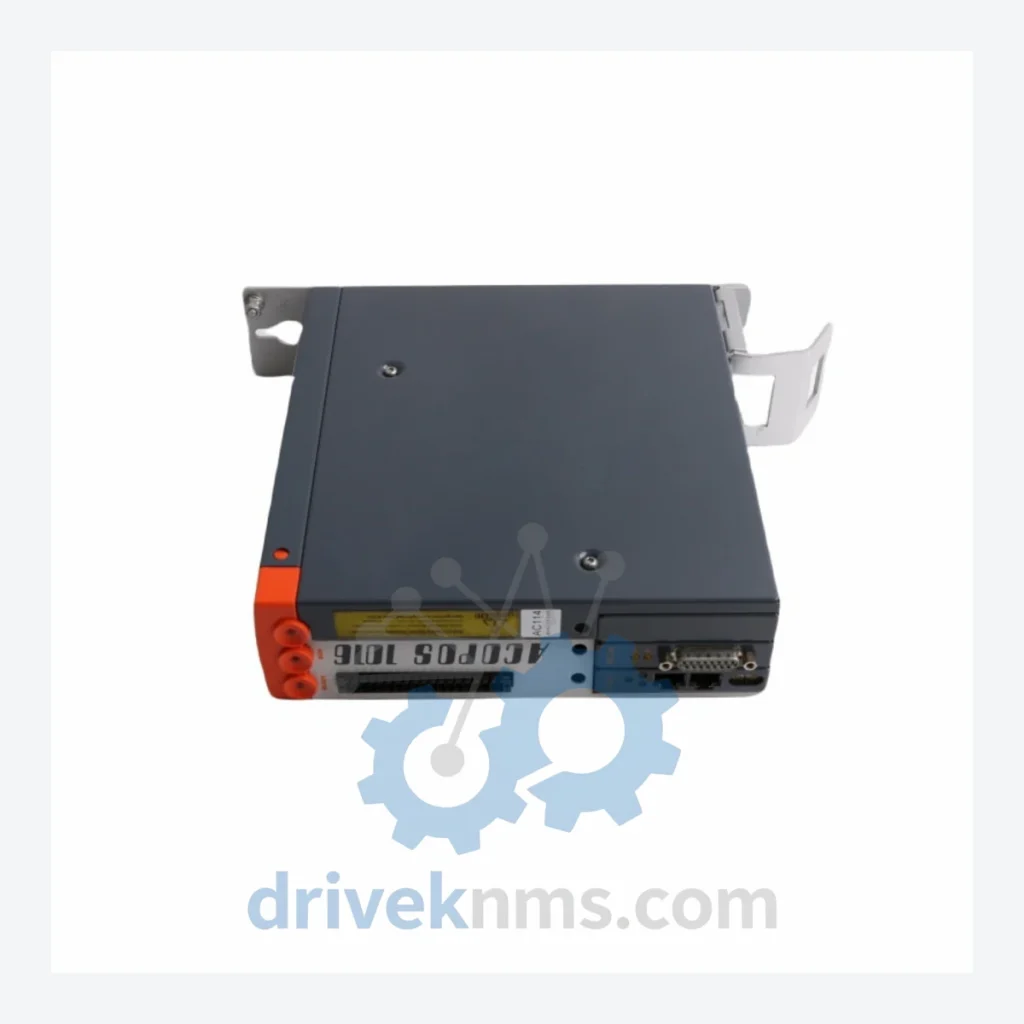
The B&R ACOPOS servo drive series is one of the most widely deployed motion control platforms in global heavy industry. Installed across chemical processing plants, nuclear facility auxiliary systems, petroleum refining operations, and large-scale automotive manufacturing lines, ACOPOS drives are recognized for their deterministic real-time performance over POWERLINK (IEC 61158) and their tight integration with B&R's Automation Studio engineering environment. The series spans single-axis and multi-axis configurations, covering output current ratings from 3 A to 320 A continuous, making it applicable from precision laboratory automation to multi-megawatt industrial drive trains. Its modular backplane architecture allows engineers to combine drive modules, plug-in cards, and system accessories within a standardized 24 VDC logic supply rail, reducing panel footprint and simplifying spare parts management across multi-site installations.
B&R introduced the original ACOPOS platform in the late 1990s as a successor to discrete servo amplifier designs, consolidating motion, safety, and fieldbus communication into a single DIN-rail-mountable unit. The first-generation 8V series established the 8V1xxx.xx-x part numbering convention still in use today, with the numeric block encoding continuous current rating and the suffix denoting hardware revision and plug-in card slot configuration.
In the mid-2000s, B&R extended the platform with the ACOPOS multi-axis variants and introduced the 8Vxxxx plug-in card ecosystem, allowing engineers to add encoder interfaces (EnDat 2.2, SSI, resolver), safety modules (SIL 2 / PLd), and additional fieldbus adapters without replacing the base drive unit. This backward-compatible expansion model is a primary reason ACOPOS installations remain in service well beyond the typical 10-year automation lifecycle.
The current generation ACOPOS P3 (8EI series) represents the architectural successor, supporting up to three axes per module and native OPC UA integration. However, the legacy 8V ACOPOS series remains in active production support and is the dominant installed base in brownfield facilities. Compatibility between 8V ACOPOS and ACOPOS P3 is not direct — motor feedback wiring, plug-in cards, and Automation Studio project configurations require migration planning when upgrading.
The following verified SKUs represent the core of the B&R ACOPOS 8V series. Classifications follow B&R's functional taxonomy: single-axis servo drives (SD), plug-in encoder/interface cards (PI), and system accessories (SA).
Single-Axis Servo Drives (SD)
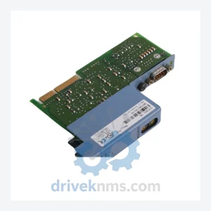
Plug-In Interface Cards (PI)
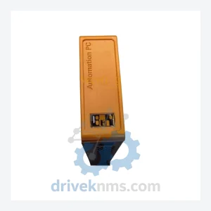
System Accessories (SA)
The B&R ACOPOS 8V series has entered the mature phase of its product lifecycle. While B&R continues to provide firmware and Automation Studio support, several plug-in card variants and lower-current drive modules have been placed on limited-availability status, with lead times from authorized distributors extending to 16–26 weeks in constrained supply periods.
ACOPOS servo drives present specific test challenges due to their integrated POWERLINK communication stack, multi-slot plug-in card backplane, and high-frequency IGBT switching stages. DriveKNMS applies a structured test protocol to all ACOPOS units prior to dispatch:
Test records are retained per unit serial number and are available to customers upon request.
© 2026 DriveKNMS. All trademarks belong to their respective owners. Specifications are for reference only and subject to change without notice. Verify all parameters against official documentation before installation.
Related Paths
B&R IF681 Series: Comprehensive Module Range and Technical Overview The B&R IF681 series is a line of interface modules developed…
B&R 5V3A0100000040-000 Programmable Logic Controller – Obsolete Legacy Spare Part When a B&R 5V3A0100000040-000 PLC module fails on an active…
B&R 5PP581.1505-00 Power Panel Touch Screen: Sourcing Strategy & Asset Return Value in a Constrained Supply Chain The B&R 5PP581.1505-00…