GE UR Series Modules: UR6AV Digital I/O Module —
GE UR Series: Comprehensive Module Range and Technical Overview The GE Grid Solutions UR Series (Universal Relay) platform is one…
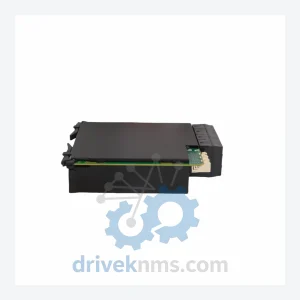
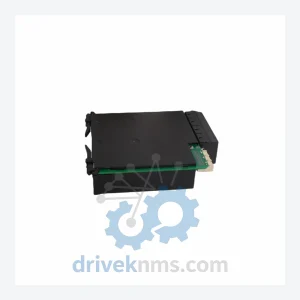
Model: BSP10 369B1879G5001
Product Overview
Commercial availability is handled through direct RFQ, model verification and export-oriented follow-up rather than public cart checkout.
Datasheet Preview
Use attached product manuals when available. If the manual is not public yet, request the full file directly through RFQ.
Commercial Path
Product pages on DRIVEKNMS are designed to verify model, brand and series first, then move the buyer into one clean quotation path.
Technical Dossier
The GE BSP10 is a numerical busbar protection relay developed by GE Grid Solutions (formerly GE Energy / Alstom Grid) for deployment in high-voltage substation environments. It is installed across critical infrastructure sectors including petrochemical complexes, nuclear power stations, offshore platforms, and large-scale oil refineries where busbar fault clearance speed is a primary safety requirement. The BSP10 operates on a centralized busbar differential protection principle, providing high-speed fault detection typically within one power frequency cycle. Its architecture supports both single and double busbar configurations, making it a standard specification in IEC 61850-compliant substations across Europe, Asia-Pacific, and the Middle East. The relay's proven track record in high-fault-current environments has sustained its installed base well into the lifecycle maintenance phase, with a significant global population of units still in active service.
The BSP10 series was introduced as part of GE's transition from electromechanical to numerical protection platforms during the late 1990s and early 2000s. Early hardware revisions used proprietary backplane communication buses with parallel wiring to current transformer (CT) input modules. Subsequent revisions introduced optical isolation on analog input channels to reduce noise susceptibility in high-interference substation environments. The relay's firmware evolved through multiple generations to support expanded bay counts and improved CT saturation detection algorithms. Compatibility between hardware generations is revision-dependent: G1 and G2 chassis are not interchangeable with G3 and later variants due to backplane connector changes. As IEC 61850 Edition 2 became the substation communication standard, later BSP10 firmware releases added GOOSE messaging support, though full IEC 61850-9-2 sampled values input was not implemented in the BSP10 generation — this capability was addressed in the successor platform. The BSP10 is now classified as a mature/end-of-active-development product. GE Grid Solutions has transitioned new project specifications to the MiCOM P740 series and the Reason RPV311 platform. However, the BSP10 remains supported under GE's long-term spares and repair program, and third-party MRO suppliers maintain stock of critical sub-assemblies.
The following SKUs represent verified components and assemblies within the GE BSP10 busbar protection relay platform. Each entry reflects a distinct hardware function within the system architecture.
369B1879G5001: BSP10 main processor and protection logic module, centralized differential calculation unit
369B1879G5002: BSP10 analog input module, 8-channel CT input board for bay current measurement
369B1879G5003: BSP10 binary input/output module, 16 DI / 8 DO for trip and alarm interfacing
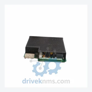
369B1879G5004: BSP10 power supply module, 110/220 V DC auxiliary supply with internal supervision
369B1879G5005: BSP10 communication interface module, RS-485 and IEC 60870-5-103 protocol support
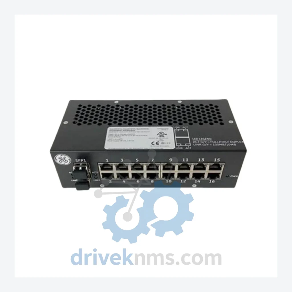
369B1879G5006: BSP10 Ethernet communication module, IEC 61850 GOOSE and MMS over 100BASE-TX
369B1879G5007: BSP10 CT input expansion module, additional 8-channel analog input for extended bay configurations
369B1879G5008: BSP10 human-machine interface (HMI) front panel module, LCD display and keypad assembly
369B1879G5009: BSP10 chassis backplane assembly, passive bus interconnect for modular card cage
369B1879G5010: BSP10 optical isolation board, analog front-end noise suppression for CT input channels
369B1879G5011: BSP10 time synchronization module, IRIG-B and PPS input for event timestamping
369B1879G5012: BSP10 redundant power supply module, hot-standby DC/DC converter for continuous operation
369B1879G5013: BSP10 trip output relay board, high-current output contacts rated for circuit breaker coil drive
369B1879G5014: BSP10 check zone module, supervisory differential element for busbar coupler bays
369B1879G5015: BSP10 end-of-life replacement kit, factory-refurbished processor and I/O assembly for legacy chassis
369B1879G5016: BSP10 firmware upgrade module, EPROM/flash carrier for field software revision update
369B1879G5017: BSP10 CT shorting and test module, in-service test facility for analog input verification
DriveKNMS maintains a dedicated inventory program for GE BSP10 components that have been discontinued from GE Grid Solutions' active production catalog. As the BSP10 platform has entered its end-of-active-manufacturing phase, procurement of specific sub-assemblies — particularly analog input boards, processor modules, and backplane assemblies — has become a critical challenge for utilities and EPC contractors managing long-term substation maintenance contracts. DriveKNMS sources BSP10 spares through a combination of decommissioned substation asset recovery, authorized surplus channels, and factory-refurbished exchange programs. All sourced units are cataloged by part number, hardware revision, and firmware version to ensure compatibility with the target chassis. For obsolete variants where new-old-stock (NOS) is unavailable, DriveKNMS offers component-level repair services performed by engineers with direct GE platform experience. Customers operating BSP10 installations under 20+ year substation lifecycle contracts are encouraged to submit their full bill-of-materials (BOM) for a consolidated availability assessment.
The BSP10's modular card-cage architecture and high-precision analog front-end require a structured test protocol that goes beyond standard power-on verification. DriveKNMS applies the following test procedures to all BSP10 units processed through its facility. Analog input accuracy is verified using a calibrated CT injection test set, confirming that each input channel meets the relay's specified measurement accuracy across the full operating current range. Backplane bus integrity is tested using a dedicated loopback fixture that validates inter-module communication at the hardware level, identifying degraded connectors or trace damage that would not be detected by functional testing alone. Binary I/O modules are tested under rated load conditions, with trip output contacts verified for contact resistance and operate time. Power supply modules are tested for output voltage stability under load step conditions and for correct operation of the internal supervision and alarm outputs. Communication modules are verified for protocol compliance using a substation automation test bench configured for IEC 60870-5-103 and IEC 61850 GOOSE. All tested units are issued a test report documenting measured values against GE's published specifications, and are shipped with ESD-protective packaging appropriate for sensitive relay electronics.
Related Paths
GE UR Series: Comprehensive Module Range and Technical Overview The GE Grid Solutions UR Series (Universal Relay) platform is one…
GE URSHB Power Supply Module – Obsolete UR Series Spare Part When a power supply module fails inside a GE…
GE UR8LV CT/VT Module – Obsolete UR Series Spare Part When a CT/VT input module fails inside a GE UR…