Sanken DKC12002B IWS HMI Touch Screen Panel – Obsolete Spare Part
Sanken DKC12002B IWS HMI Touch Screen Panel – Obsolete Spare Part When a Sanken DKC12002B IWS touch screen panel fails…
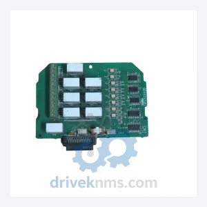
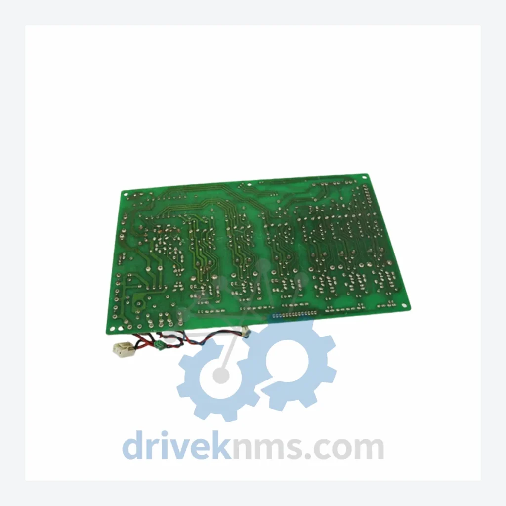
Model: DK14256A
Product Overview
Commercial availability is handled through direct RFQ, model verification and export-oriented follow-up rather than public cart checkout.
Datasheet Preview
Use attached product manuals when available. If the manual is not public yet, request the full file directly through RFQ.
Commercial Path
Product pages on DRIVEKNMS are designed to verify model, brand and series first, then move the buyer into one clean quotation path.
Technical Dossier
The Sanken DK14256A is a purpose-built circuit board module deployed across heavy industrial sectors including petrochemical processing plants, power generation facilities, steel manufacturing lines, and water treatment infrastructure. Sanken Electric Co., Ltd. (Japan) has maintained a consistent presence in industrial power electronics since the 1940s, and the DK-series circuit boards represent the company's application-specific control and drive interface layer used in variable frequency drives (VFDs), servo amplifiers, and motor control centers (MCCs). The DK14256A specifically functions as a control/driver interface board within Sanken's inverter and drive product families, providing gate drive signal conditioning, fault detection logic, and inter-board communication between the main control PCB and the power module stack. Its deployment in long-lifecycle industrial assets means demand for replacement units persists well beyond the product's active production window.
Sanken's DK-series circuit boards evolved through several design generations tied to the company's inverter drive platform revisions. Early DK-series boards (pre-2000) used through-hole component construction with discrete optocoupler isolation and analog fault threshold circuits. Mid-generation boards (2000–2012) transitioned to surface-mount technology (SMT), integrating dedicated gate driver ICs (e.g., Sanken STK series hybrids) and digital fault latch logic. The DK14256A belongs to this SMT-dominant generation, characterized by a compact multilayer PCB layout, onboard EEPROM for parameter storage, and standardized 24-pin or 26-pin edge connectors for backplane integration. Later revisions introduced conformal coating for humidity resistance in coastal and chemical plant environments. Compatibility between sub-generations is connector-dependent; firmware revision mismatches between the DK14256A and the host drive's main CPU board can trigger fault codes F-01 through F-09 on Sanken SI/SIE-series drives. Cross-referencing the drive's nameplate revision code against the board's silk-screened revision marking (REV.A through REV.D) is mandatory before substitution.
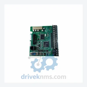
The following SKUs represent verified Sanken DK-series and associated circuit board part numbers commonly found in industrial drive and inverter systems. Each entry reflects a distinct functional role within the drive architecture:
Each DK14256A unit processed by DriveKNMS undergoes a structured inspection and functional test protocol specific to gate driver and control interface boards:
Related Paths
Sanken DKC12002B IWS HMI Touch Screen Panel – Obsolete Spare Part When a Sanken DKC12002B IWS touch screen panel fails…
KEB COMBIVERT F5 Series: Comprehensive Module Range and Technical Overview The KEB COMBIVERT F5 is a general-purpose AC variable frequency…
Sanken DMC12008 CPU Board – Obsolete Sanken Legacy Spare Part When a CPU board fails in a legacy Sanken-controlled production…