VACON NX Series Control Boards
VACON NX Series: Comprehensive Control Board Range and Technical Overview The VACON NX series of AC drives and associated control/option…
Model: PC00459G
Product Overview
Commercial availability is handled through direct RFQ, model verification and export-oriented follow-up rather than public cart checkout.
Datasheet Preview
Use attached product manuals when available. If the manual is not public yet, request the full file directly through RFQ.
Commercial Path
Product pages on DRIVEKNMS are designed to verify model, brand and series first, then move the buyer into one clean quotation path.
Technical Dossier
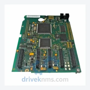
The Vacon PC Series encompasses the internal control, trigger, and gate-driver printed circuit board assemblies used across Vacon's NX, NXP, NXL, and legacy 100-series AC variable frequency drives. These drives are deployed at scale in heavy-process industries including petrochemical refining, nuclear auxiliary systems, offshore platform motor control, pulp and paper mills, and municipal water treatment. The PC Series boards occupy the critical signal-processing and power-switching interface layer within the drive stack: they translate control-layer commands into precise IGBT gate pulses, manage DC bus feedback, and execute protection logic for overcurrent, overvoltage, and thermal events. Because Vacon drives are engineered for 20+ year service lives, the PC Series spare parts market remains active long after individual board revisions reach end-of-production status.
Vacon's drive board architecture evolved through three distinct generations. The first generation (mid-1990s to early 2000s) used discrete gate-driver circuits with through-hole component construction; boards from this era include early PC00xxx-series identifiers and are now fully obsolete with no OEM support. The second generation (2003–2012) introduced surface-mount technology, integrated IGBT driver ICs, and fiber-optic isolation between the control board and the power stage; the PC00459G belongs to this generation and remains one of the most widely requested trigger boards for NX-series drives in the 45–160 kW power range. The third generation (2013–present), associated with the Vacon 100 and Vacon 100 FLOW platforms, uses a unified control board architecture with embedded fieldbus support and onboard PLC functionality. Compatibility between generations is not interchangeable: backplane connectors, firmware handshake protocols, and gate-driver voltage levels differ. Facilities running second-generation NX drives must source generation-matched boards; substituting third-generation assemblies will result in drive fault and potential IGBT damage.
The following SKUs represent verified, commonly sourced Vacon PC Series control and trigger board assemblies. Each entry reflects a distinct functional role within the drive architecture.
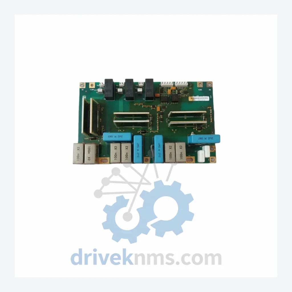
PC00459G: NX series IGBT trigger/gate-driver board, 45–160 kW frame size, fiber-optic isolated gate pulse output.
PC00459C: Earlier revision of the NX trigger board; compatible with lower-revision NX power stacks; superseded by PC00459G.
PC00459D: Intermediate revision trigger board for NX drives; used in specific regional production batches 2005–2008.
PC00459E: Revision E trigger board; introduced enhanced short-circuit protection response time vs. revision D.
PC00459F: Revision F; updated gate resistor values for improved EMC compliance in NX 75–132 kW frames.
PC00458C: Lower-power NX trigger board variant for 1.5–22 kW frame sizes; separate gate-driver topology from PC00459 family.
PC00458D: Revision D of the small-frame trigger board; improved thermal pad interface for heatsink contact.
PC00460B: NXP (heavy-duty) series trigger board for 200–355 kW frames; dual IGBT module gate-driver configuration.
PC00460C: Revision C NXP trigger board; added redundant overcurrent latch circuit for high-inertia load applications.
PC00461A: NX control board (NXOPTA1); handles speed reference, PID, and I/O logic; interfaces with trigger board via ribbon connector.
PC00462B: NX option board slot carrier; supports fieldbus adapter modules (PROFIBUS, DeviceNet, Modbus TCP).
PC00463A: NX power supply board; generates ±15 V and +5 V rails for control electronics from DC bus.
PC00464C: NX brake chopper control board; manages dynamic braking IGBT switching for regenerative load applications.
PC00465A: NX fan control and thermal monitoring board; interfaces with drive heatsink NTC sensors and cooling fan relay.
PC00466B: NXL (lite) series main control board; integrated I/O and gate-driver on single PCB for compact drive frames.
PC00467A: NX EMC filter interface board; used in IP54-rated enclosure variants for outdoor and marine installations.
PC00468C: NXP high-power DC bus capacitor balancing board; used in parallel IGBT module configurations above 400 kW.
Vacon (acquired by Danfoss in 2014) has progressively discontinued OEM spare parts support for NX-series boards manufactured before 2010. Revision letters A through E of the PC00459 family are no longer available through authorized Danfoss distribution channels. DriveKNMS maintains a dedicated inventory of tested, pull-out, and remanufactured PC Series boards sourced from decommissioned drive units, controlled-environment warehouses, and verified secondary-market suppliers. For facilities operating under long-term maintenance contracts or regulated environments (nuclear, offshore, water utility), DriveKNMS provides board-level traceability documentation including revision history, test date, and functional verification records. Minimum lead time for in-stock units is 1–3 business days; sourcing lead time for non-stocked revisions is 7–21 business days depending on global inventory availability.
Vacon PC Series trigger boards require functional validation beyond basic visual inspection due to the precision timing requirements of IGBT gate-drive signals. DriveKNMS applies the following test protocol to all PC Series boards prior to dispatch. Each board undergoes automated in-circuit test (ICT) to verify passive component values and solder joint integrity. Gate-driver output channels are tested under resistive load at rated gate voltage (typically ±15 V) with pulse-width and dead-time measurements verified against OEM specification sheets. Fiber-optic transmitter and receiver pairs are tested for signal integrity and propagation delay. DC isolation resistance between gate-driver output and control-side logic is measured at 500 V DC to confirm creepage compliance. Boards that pass all stages are labeled with a DriveKNMS QC serial number and test date. Boards with repairable faults (failed gate resistors, degraded optocouplers) are repaired using OEM-equivalent components and re-tested through the full protocol before release.
Related Paths
VACON NX Series: Comprehensive Control Board Range and Technical Overview The VACON NX series of AC drives and associated control/option…
VACON PC00225I Power Supply Board: Global Sourcing Strategy & Asset Return Value The VACON PC00225I is a power supply board…
ALSTOM MVAJ105RA0802A Protection Relay: Supply Continuity Strategy for a Discontinued Critical Component The ALSTOM MVAJ105RA0802A is a numerical protection relay…