
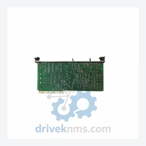
Yokogawa K9634DA-01 TCD Card Modules
Yokogawa K9634DA-01 is listed for Servo Drives RFQ review. Confirm quantity, condition and destination before quotation.
RFQ-ready industrial model
Model: AMN32 S1
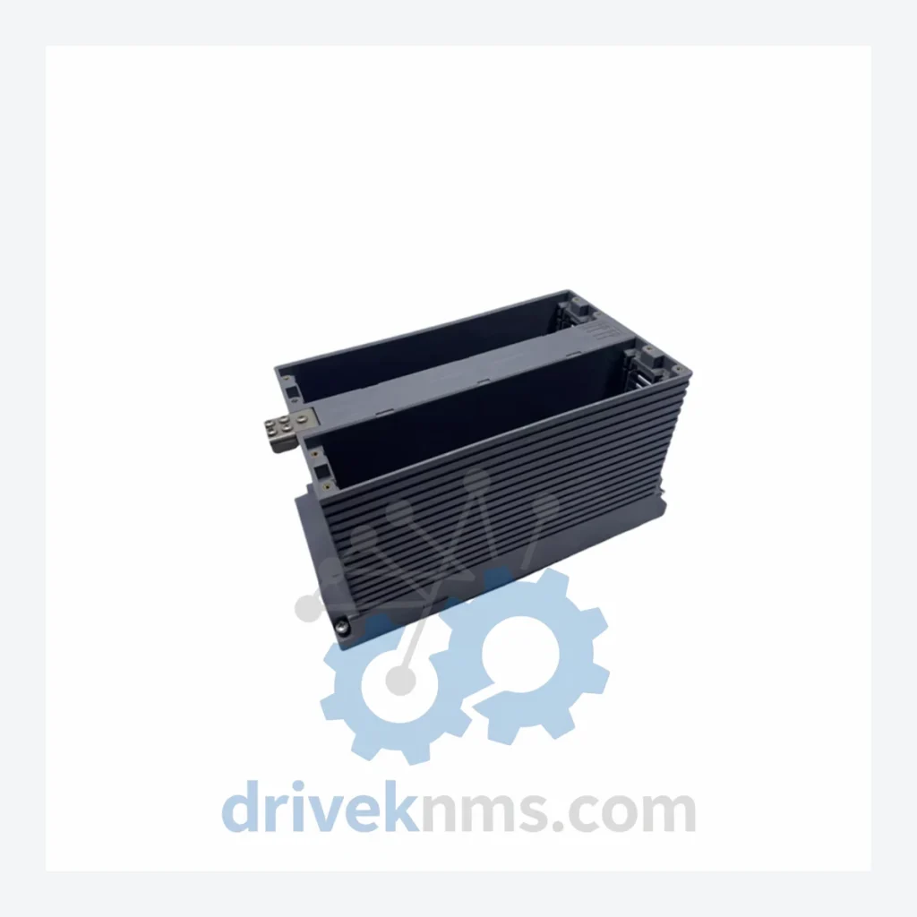
Product Overview
Commercial availability is handled through direct RFQ, model verification and export-oriented follow-up rather than public cart checkout.
Datasheet Preview
Use attached product manuals when available. If the manual is not public yet, request the full file directly through RFQ.
Commercial Path
Product pages on DRIVEKNMS are designed to verify model, brand and series first, then move the buyer into one clean quotation path.
Technical Dossier
The AMN Series was introduced as part of YOKOGAWA's CENTUM CS platform in the mid-1990s, succeeding the earlier CENTUM-XL I/O infrastructure. The original CS-era modules used a parallel backplane bus with fixed-slot addressing. With the transition to CENTUM CS 3000 (released 1998), YOKOGAWA standardized the AMN form factor around a 32-channel density target and introduced dual-redundancy options for critical analog inputs. The subsequent CENTUM VP platform (released 2008) maintained backward hardware compatibility with the majority of AMN modules, allowing existing installations to migrate to VP software without full hardware replacement — a key factor in the series' longevity in the field.
By the mid-2010s, YOKOGAWA began transitioning new projects toward the CENTUM VP R6 architecture with enhanced cybersecurity features and Ethernet-based I/O. However, the installed base of AMN modules across legacy CS 3000 and early VP systems remains substantial. Many of these modules have entered the manufacturer's end-of-active-support phase, creating demand for third-party lifecycle extension services. Compatibility issues arise primarily when mixing S1 and S2 hardware revisions within the same node, and when substituting modules across different FCS generations without firmware alignment.
The following SKUs represent verified members of the YOKOGAWA AMN Series I/O module family. Models are classified by function type.
Analog Input (AI) Modules
AMN11: 16-ch analog input, 4–20 mA, non-isolated, standard density
AMN12: 16-ch analog input, 4–20 mA, with HART communication support
AMN21: 32-ch analog input, 4–20 mA, high-density, non-isolated
AMN22: 32-ch analog input, 4–20 mA, HART-enabled, high-density
AMN31: 16-ch analog input, thermocouple/RTD, temperature measurement
AMN32 S1: 32-ch analog input, thermocouple/RTD, high-density temperature module, S1 hardware revision — the subject SKU of this listing
AMN33: 16-ch analog input, millivolt/thermocouple, extended range
Analog Output (AO) Modules
AMN51: 8-ch analog output, 4–20 mA, standard resolution
AMN52: 16-ch analog output, 4–20 mA, high-density
AMN53: 8-ch analog output, 4–20 mA, with HART communication
Digital Input (DI) Modules
AMN61: 32-ch digital input, 24 VDC, dry contact / wet contact selectable
AMN62: 64-ch digital input, 24 VDC, high-density discrete input
AMN63: 32-ch digital input, 110/220 VAC, high-voltage discrete input
Digital Output (DO) Modules
AMN71: 16-ch digital output, 24 VDC, transistor output
AMN72: 32-ch digital output, 24 VDC, high-density transistor output
AMN73: 16-ch digital output, relay contact, isolated output
Communication / Specialty Modules
AMN81: Node interface module, FCS-to-I/O bus bridge, redundancy-capable
AMN91: Power supply module for AMN node, 24 VDC regulated output
AMN Series modules present specific test challenges due to their multi-channel analog bus architecture and backplane-dependent initialization sequences. DriveKNMS applies the following verification protocol to all AMN Series units prior to dispatch:
Backplane Bus Integrity Test: Each module is seated in a live CENTUM CS 3000 or VP test rack and subjected to full FCS enumeration. Modules that fail to register on the V-net/IP or ESB bus are rejected.
Channel-Level Signal Verification: For AI modules including the AMN32 S1, all 32 channels are individually stimulated with calibrated mA or thermocouple equivalent signals. Output linearity and cold-junction compensation accuracy are recorded.
Isolation Resistance Check: Channel-to-channel and channel-to-backplane isolation is measured at 500 VDC. Minimum acceptable threshold: 100 MΩ.
Revision Marking Audit: Hardware revision labels (S1/S2) are cross-referenced against internal PCB revision markings to detect remarked or misrepresented units.
Burn-In Cycle: Units are operated continuously for 48 hours under simulated process load before final inspection and packaging.
Continue The Model Path
Move from this exact model into the matching system hub, brand archive, model-family archive or lifecycle sourcing route before sending a final RFQ list.
Related Paths
Yokogawa K9634DA-01 is listed for Servo Drives RFQ review. Confirm quantity, condition and destination before quotation.
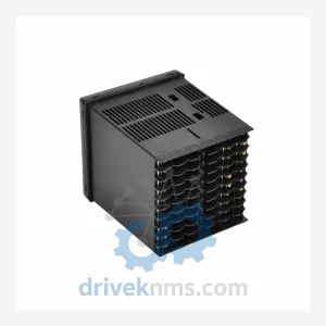
Yokogawa UT350 UT350-01 is listed for Servo Drives RFQ review. Confirm quantity, condition and destination before quotation.
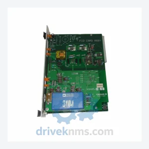
Yokogawa K9403JA-02 is listed for Servo Drives RFQ review. Confirm quantity, condition and destination before quotation.