FUJI EP Series Modules: EP-3429-C6-Z2
Fuji Electric EP Series: Comprehensive Module Range and Technical Overview The Fuji Electric EP Series represents a mature, field-proven platform…
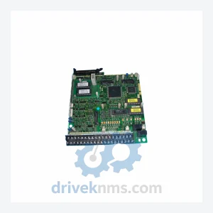
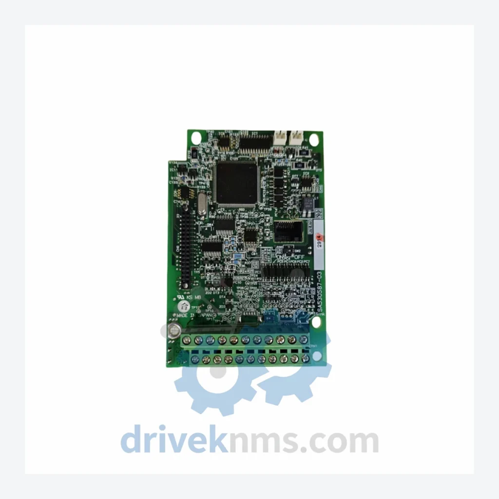
Model: SA531121-03 E11-C4PCB
Product Overview
Commercial availability is handled through direct RFQ, model verification and export-oriented follow-up rather than public cart checkout.
Datasheet Preview
Use attached product manuals when available. If the manual is not public yet, request the full file directly through RFQ.
Commercial Path
Product pages on DRIVEKNMS are designed to verify model, brand and series first, then move the buyer into one clean quotation path.
Technical Dossier
The FUJI SA531121-03 series drive boards are core printed circuit board assemblies deployed within FUJI Electric's industrial inverter and servo drive platforms. These boards are installed across heavy-industry sectors including petrochemical plants, nuclear power auxiliary systems, offshore oil refineries, steel rolling mills, and large-scale water treatment facilities. The SA531121-03 designation identifies a specific gate-drive and control PCB lineage used in FUJI FRENIC and related drive families, where board-level reliability directly governs motor control continuity in mission-critical processes. Global installed base data confirms that FUJI drive boards of this series remain active in facilities with 15–25 year equipment lifecycles, making spare part availability a primary operational concern for maintenance engineers worldwide.
The SA531121-03 board architecture traces its lineage to FUJI Electric's early FRENIC5000 inverter platform, introduced in the late 1980s and progressively refined through the FRENIC-Mega, FRENIC-Multi, and FRENIC-Ace generations. Early revisions of the SA531121 series used through-hole component construction with discrete IGBT gate-drive circuits. Subsequent engineering revisions (E5, E7, E9, E11) transitioned to surface-mount technology (SMT), integrating optocoupler isolation stages and on-board current sensing directly onto the PCB substrate. The E11 revision — as found in the SA531121-03 E11-C4PCB — represents a mature, high-density layout with enhanced EMI shielding traces and improved thermal pad design for the gate-drive ICs. Compatibility across revisions is not guaranteed: backplane connector pinouts and firmware handshake protocols differ between E-series generations, requiring exact revision matching during replacement. As FUJI Electric has transitioned its current product line toward the FRENIC-Ace II and FRENIC-HVAC platforms, the SA531121-03 series has entered the mature/end-of-life phase, making third-party lifecycle support essential for continued operation.
The following SKUs represent verified models within the FUJI SA531121-03 drive board family and associated PCB assemblies used in the same inverter platform generation. Each entry reflects a distinct functional role within the drive system:
SA531121-03 E11-C4PCB: Main gate-drive control PCB, E11 revision, C4 power class.
SA531121-03 E09-C4PCB: Gate-drive PCB, E09 revision, predecessor to E11 layout.
SA531121-03 E07-C4PCB: Early SMT gate-drive board, E07 revision, C4 frame.
SA531121-03 E05-C2PCB: Through-hole gate-drive PCB, E05 revision, C2 power class.
SA531121-01 E11-C4PCB: Variant -01 suffix; alternate BOM for specific regional market configurations.
SA531121-02 E11-C4PCB: Variant -02 suffix; modified snubber circuit layout for high-humidity environments.
SA531121-04 E11-C4PCB: Variant -04 suffix; extended temperature range gate-drive board.
SA531121-03 E11-C2PCB: C2 power class variant of the E11 revision; used in lower-kW drive frames.
SA531121-03 E11-C6PCB: C6 power class variant; high-current gate-drive for large-frame inverters.
EP-3764B: Associated power supply PCB used in the same FUJI drive chassis generation.
EP-3765A: Auxiliary control interface board, cross-compatible with SA531121-03 chassis.
SA371121-01: Predecessor series gate-drive board; functionally equivalent in early FRENIC5000 frames.
SA371121-03: Revised predecessor; used in transitional FRENIC5000G11S platforms.
SA531122-01 E11-C4PCB: Adjacent series; current-feedback PCB paired with SA531121-03 in dual-board configurations.
SA531123-01 E11-C4PCB: Communication interface PCB; installed alongside SA531121-03 in networked drive systems.
SA531124-01: Encoder feedback processing board; used in servo-mode FUJI drive configurations.
SA531125-02: Brake control PCB; paired with SA531121-03 in hoist and crane drive applications.
DriveKNMS maintains a dedicated inventory program for end-of-life FUJI drive boards, including the full SA531121-03 revision range. As FUJI Electric no longer manufactures E05 through E09 revision boards through standard distribution channels, procurement of these assemblies requires access to verified surplus stock, factory-refurbished units, or component-level repair services. DriveKNMS sources SA531121-03 boards through a network of decommissioned plant equipment, authorized surplus dealers, and direct factory-overstock channels in Japan and Southeast Asia. Each unit is catalogued by revision code, power class suffix, and date code before entering inventory. For facilities operating legacy FRENIC or FRENIC5000 platforms, DriveKNMS provides cross-reference matching to identify compatible substitute revisions where exact-match stock is unavailable, minimizing unplanned downtime during emergency maintenance events.
Drive boards in the SA531121-03 series present specific test challenges due to their integrated gate-drive optocoupler arrays, multi-layer PCB construction, and revision-dependent firmware interfaces. DriveKNMS applies the following verification protocol to all SA531121-03 units prior to dispatch: (1) Visual inspection under 10× magnification for solder joint integrity, delamination, and component displacement. (2) In-circuit resistance measurement across gate-drive output stages to detect failed optocouplers or shorted IGBT driver ICs. (3) Functional power-up test using a controlled bench inverter chassis matching the target power class (C2, C4, or C6), with monitored gate-pulse output verification at rated switching frequency. (4) Thermal cycling test (−10°C to +70°C, 3 cycles) to identify latent cold-solder failures common in aged SMT assemblies. (5) Revision code and BOM verification against FUJI Electric service documentation to confirm exact-match specification before shipment. Units that do not pass all five stages are either returned for component-level rework or classified as non-serviceable and removed from inventory.
Related Paths
Fuji Electric EP Series: Comprehensive Module Range and Technical Overview The Fuji Electric EP Series represents a mature, field-proven platform…
FUJI EP-3364B-CA-Z2 Inverter Control Board: Supply Continuity Strategy for a Discontinued Critical Spare The FUJI EP-3364B-CA-Z2 is a control board…
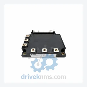
Fuji Electric 7MBI Series: Comprehensive Module Range and Technical Overview The Fuji Electric 7MBI series represents one of the most…