
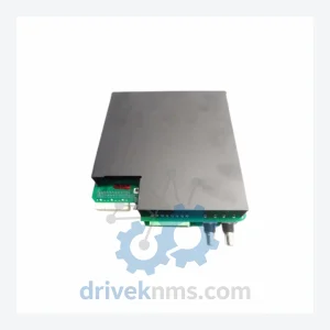
GE Grid Solutions UR9EV CPU Module
GE Grid Solutions UR9EV is listed for PLC Modules RFQ review. Confirm quantity, condition and destination before quotation.
RFQ-ready industrial model
Model: 369B1844G5004
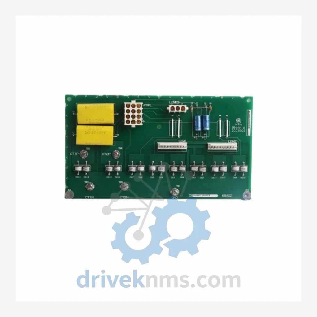
Product Overview
Commercial availability is handled through direct RFQ, model verification and export-oriented follow-up rather than public cart checkout.
Datasheet Preview
Use attached product manuals when available. If the manual is not public yet, request the full file directly through RFQ.
Commercial Path
Product pages on DRIVEKNMS are designed to verify model, brand and series first, then move the buyer into one clean quotation path.
Technical Dossier
DriveKNMS reviews sourcing status and documentation for this model during RFQ handling before quotation.
RFQ support for obsolete parts: Send the model number, required quantity and destination so DriveKNMS can confirm sourcing options before quotation.
| Part Number | 369B1844G5004 |
| Manufacturer | GE Grid Solutions (formerly GE Multilin) |
| Series | Multilin 369 Motor Management Relay |
| Module Type | Relay Output Module |
| Product Status | Discontinued / Obsolete – No longer in production |
| Compatible Platform | GE Multilin 369 Motor Management Relay |
| Country of Origin | United States |
| Typical Application | Motor protection relay output expansion in MCC panels, industrial motor control centers |
Note: Electrical parameters such as contact ratings and coil specifications are not published here to avoid inaccuracy. Please contact us directly for verified datasheet documentation.
The GE Multilin 369 platform was deployed extensively across oil & gas, water treatment, mining, and heavy manufacturing facilities throughout the 1990s and 2000s. Its motor protection logic — overcurrent, undercurrent, thermal overload, ground fault — was engineered into site-specific protection schemes that took years to calibrate and validate. The relay output module 369B1844G5004 is the physical interface between that protection logic and the field contactors, breakers, and alarm systems it controls.
There is no software patch for a failed relay output module. There is no firmware workaround. When this module fails, the motor protection circuit is compromised. In a best-case scenario, the motor trips offline and production halts. In a worst-case scenario, the protection gap goes undetected until a motor failure causes equipment damage or a safety incident.
Replacing the entire 369 relay system to resolve a single module failure is an engineering decision that cannot be justified on cost grounds alone. The 369B1844G5004 is the correct, proportionate response to this failure mode. It restores the protection circuit without disturbing the surrounding system architecture, without requiring re-engineering of protection settings, and without triggering a capital expenditure review cycle.
Facilities that have adopted a proactive spare parts strategy for their Multilin 369 installations report sustained system availability well beyond the manufacturer's intended service life. A single spare module held in a climate-controlled store room has, in documented cases, deferred a six-figure system replacement by five to ten years.
Sourcing obsolete relay output modules from the secondary market carries real risk. DriveKNMS applies a structured 5-step inspection protocol to every unit before it is offered for sale:
Step 1 – Visual and Mechanical Inspection: Full examination of the module housing, connector pins, and PCB surface. Any evidence of physical damage, burn marks, or corrosion results in immediate rejection.
Step 2 – Electrolytic Capacitor Assessment: Aged electrolytic capacitors are the primary failure mode in legacy relay modules. Each unit is assessed for capacitor bulging, leakage, and ESR degradation. Units with suspect capacitors are either reconditioned with verified replacements or rejected.
Step 3 – Pin and Connector Integrity Check: Relay output modules are subject to repeated insertion cycles and environmental contamination. All connector pins are inspected for oxidation, deformation, and contact resistance. Corroded contacts are treated or the unit is rejected.
Step 4 – Firmware and Label Verification: Where applicable, firmware version markings and hardware revision labels are cross-referenced against known production records to confirm authenticity and compatibility.
Step 5 – Functional Verification: Units are powered and output relay operation is confirmed prior to packaging.
Units that pass all five stages are classified as Tested Surplus or Refurbished, clearly documented, and shipped with full inspection records.
This matters because the alternative — a full relay replacement — triggers a cascade of engineering work: new relay selection, protection coordination study, factory acceptance testing, site acceptance testing, and operator retraining. That process routinely takes three to six months and consumes engineering budgets that were not allocated for this purpose. The 369B1844G5004 eliminates that cascade entirely.
Continue The Model Path
Move from this exact model into the matching system hub, brand archive, model-family archive or lifecycle sourcing route before sending a final RFQ list.
Related Paths
GE Grid Solutions UR9EV is listed for PLC Modules RFQ review. Confirm quantity, condition and destination before quotation.
GE Grid Solutions UR 9GH is listed for PLC Modules RFQ review. Confirm quantity, condition and destination before quotation.
GE Grid Solutions UR9KH is listed for UR Series RFQ review. Confirm quantity, condition and destination before quotation.