
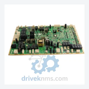
GE IS200WETBH1BAA Elevator Control Board – Obsolete Speedtronic Spare Part
General Electric IS200WETBH1BAA is listed for Controller Cards RFQ review. Confirm quantity, condition and destination before quotation.
RFQ-ready industrial model
Model: DS200QTBDG1AAA
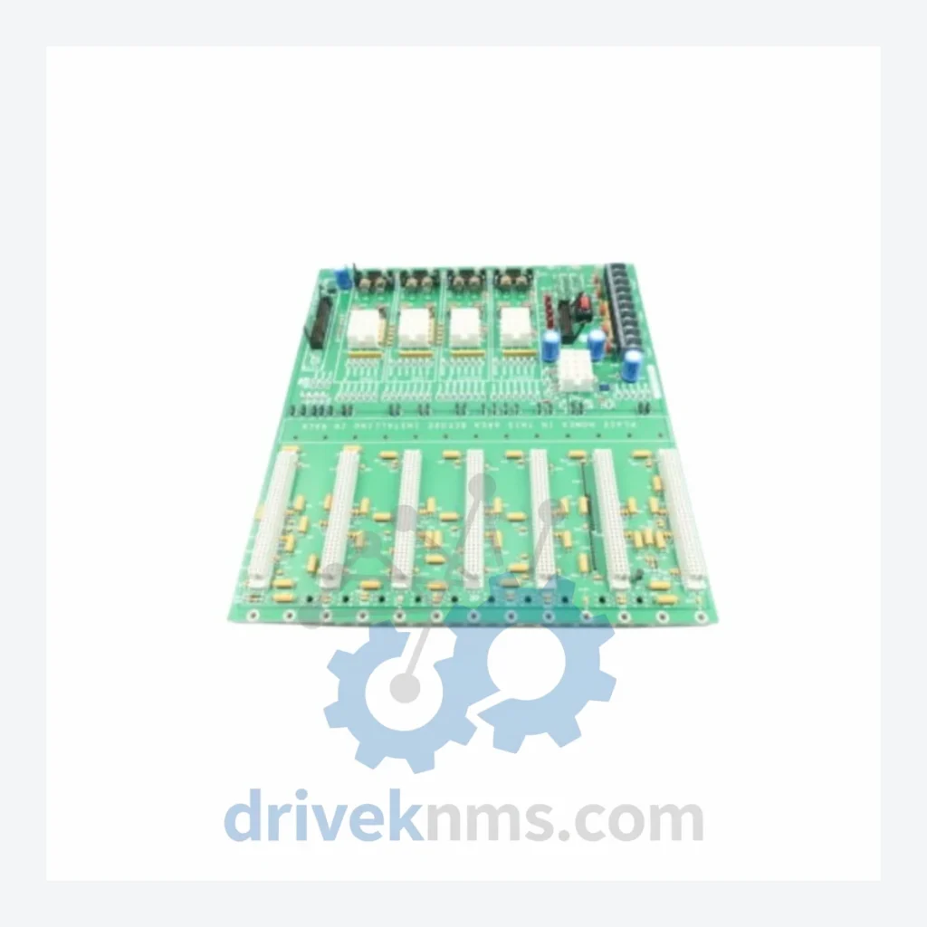
Product Overview
Commercial availability is handled through direct RFQ, model verification and export-oriented follow-up rather than public cart checkout.
Datasheet Preview
Use attached product manuals when available. If the manual is not public yet, request the full file directly through RFQ.
Commercial Path
Product pages on DRIVEKNMS are designed to verify model, brand and series first, then move the buyer into one clean quotation path.
Technical Dossier
The GE DS200 series constitutes the core I/O, control, and communication hardware platform for GE's Mark V and Mark VI turbine control systems. Deployed across heavy industrial sectors — including petrochemical refineries, nuclear power stations, combined-cycle gas turbine plants, and offshore platforms — DS200 boards are embedded in critical control loops governing fuel metering, exhaust temperature management, vibration monitoring, and emergency shutdown sequences. The installed base of Mark V and Mark VI systems globally numbers in the tens of thousands of units, the majority of which remain in active service well beyond their original design lifecycle. This creates a sustained, high-demand aftermarket for DS200 spare parts that cannot be substituted with off-the-shelf alternatives.
The DS200 hardware lineage originates with the Mark V Turbine Control System, introduced by GE in the late 1980s as a successor to the Mark IV relay-based platform. Mark V employed a triple-redundant TMR (Triple Modular Redundancy) architecture across three independent control processors — , , and — with DS200 boards serving as the physical interface layer between the control core and field instrumentation. The backplane communication protocol used a proprietary serial bus (IONet) that is not compatible with standard industrial Ethernet or Profibus standards.
In the late 1990s, GE introduced the Mark VI, which retained physical compatibility with many DS200 I/O boards but migrated the communication backbone to a dual-redundant Ethernet IONet topology. This transition created a mixed-generation installed base in which DS200 boards manufactured for Mark V may be physically installed in Mark VI racks but require firmware and jumper configuration verification before substitution. The Mark VIe, introduced in the 2000s, further migrated to a distributed I/O architecture using IS200-series boards, rendering DS200 hardware a legacy-but-critical category. GE (now part of GE Vernova) no longer manufactures DS200 boards; all procurement is sourced through authorized aftermarket distributors and certified repair facilities.
The following SKUs represent verified, commonly sourced DS200 series components. Each entry reflects the board's primary functional role within the Mark V/VI control architecture.
DS200QTBDG1AAA: Digital contact terminal board; interfaces discrete field contacts to the Mark V I/O processor via optically isolated inputs.
DS200TCQAG1BHF: Turbine control quad analog I/O board; processes four analog input/output channels for speed and load control loops.
DS200SDCIG2AFA: Speed and direction control interface board; decodes magnetic pickup signals for turbine shaft speed measurement.
DS200TCPSG1AME: Turbine control power supply board; provides regulated DC voltages to the Mark V control core and I/O racks.
DS200DSPCH1ADA: Digital signal processor communication board; manages high-speed data exchange between the TMR control processors.
DS200TCEAG1BHF: Turbine control excitation analog board; interfaces generator excitation control signals to the Mark V system.
DS200SLCCG3ADB: Sequence logic control card; executes ladder-logic sequences for start/stop permissive and alarm management.
DS200IOCAG1A: I/O controller analog board; aggregates analog field signals from thermocouples and RTDs for temperature monitoring.
DS200TBCIH1C: Terminal board for current inputs; provides screw-terminal field wiring interface for 4–20 mA current loop signals.
DS200EXPSG1ADA: Expansion power supply board; extends DC power distribution capacity within high-density I/O rack configurations.
DS200DTBCG1AAA: Digital terminal board for contact inputs; supports up to 24 discrete field contact inputs per board slot.
DS200VPBLG1AFF: Vibration and proximity board; conditions and digitizes proximity probe signals for shaft vibration monitoring.
DS200GDDAG1AEB: Generator differential protection analog board; processes differential current signals for generator protection relay functions.
DS200TCCAG1BHF: Turbine control communication analog board; bridges analog I/O data to the Mark V serial communication bus.
DS200PCCAG1ABB: Process control communication analog board; interfaces process analog signals to the Mark V control processor for balance-of-plant loops.
DS200FCGDH1BHF: Fuel control and gas detection board; monitors combustible gas detector inputs and interfaces fuel valve actuator signals.
DS200 boards present specific testing challenges due to their proprietary backplane bus architecture and the absence of publicly available GE test specifications. DriveKNMS applies a structured multi-stage verification protocol to all DS200 units prior to dispatch:
Visual Inspection: All boards undergo 10× magnification inspection for capacitor bulge, PCB delamination, solder joint cracking, and corrosion on edge connectors — failure modes common in boards recovered from high-humidity or high-vibration environments.
Component-Level Testing: Optocouplers, voltage regulators, and EEPROM devices are tested individually using bench instruments before board-level power-on.
Functional Bench Test: Where test fixtures are available, boards are powered in a controlled rack environment and exercised through their I/O channels using signal generators and load simulators to verify channel-by-channel functionality.
Communication Bus Verification: For boards with IONet or serial bus interfaces, communication integrity is verified using protocol analyzers to confirm correct framing, addressing, and response timing.
Burn-In: Repaired or refurbished units undergo a minimum 48-hour thermal burn-in cycle to screen for early-life component failures before dispatch review.
Continue The Model Path
Move from this exact model into the matching system hub, brand archive, model-family archive or lifecycle sourcing route before sending a final RFQ list.
Related Paths
General Electric IS200WETBH1BAA is listed for Controller Cards RFQ review. Confirm quantity, condition and destination before quotation.
General Electric IS200TRLYH1BED IS200TRLYH1B is listed for Controller Cards RFQ review. Confirm quantity, condition and destination before quotation.
General Electric IS230SNRLH2A IS200SRLYH2AAA is listed for Controller Cards RFQ review. Confirm quantity, condition and destination before quotation.