
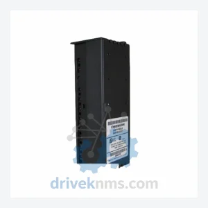
GE IC660 Genius I/O Modules IC660EBA026
GE Automation & Controls IC660EBA026 is listed for Genius I/O RFQ review. Confirm quantity, condition and destination before quotation.
RFQ-ready industrial model
Model: IC660BBR101
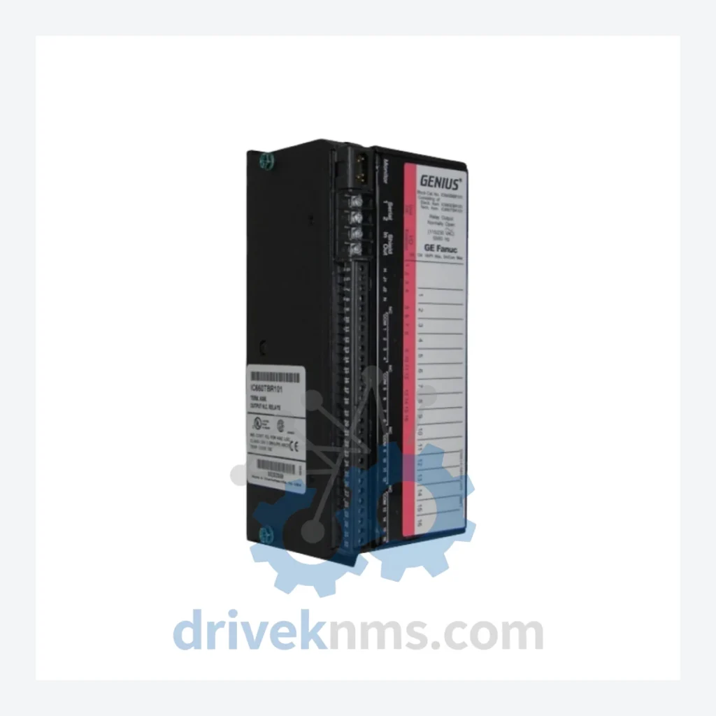
Product Overview
Commercial availability is handled through direct RFQ, model verification and export-oriented follow-up rather than public cart checkout.
Datasheet Preview
Use attached product manuals when available. If the manual is not public yet, request the full file directly through RFQ.
Commercial Path
Product pages on DRIVEKNMS are designed to verify model, brand and series first, then move the buyer into one clean quotation path.
Technical Dossier
The GE IC660 Genius I/O series is a distributed I/O platform developed by General Electric (later GE Fanuc Automation) and deployed extensively across global heavy industry sectors including petrochemical refineries, nuclear power generation facilities, offshore oil & gas platforms, pulp and paper mills, and continuous process manufacturing plants. The series operates on the Genius Bus — a single-wire, token-passing serial fieldbus — enabling deterministic, high-speed communication between field devices and host controllers such as the GE Series 90-70 and Series 90-30 PLCs. Its modular architecture, rugged industrial enclosure ratings, and long production lifecycle made it a standard specification in large-scale DCS and hybrid control architectures throughout the 1990s and 2000s. Installed base counts in the tens of thousands of nodes globally, and the series remains in active service at facilities with 20–30 year asset lifecycles.
The IC660 Genius I/O architecture was introduced in the mid-1980s as GE's answer to the growing demand for distributed field I/O in large process plants. The original Genius Bus operated at 153.6 kbaud over a shielded twisted-pair cable, supporting up to 32 devices per bus segment with a maximum cable length of 7,500 feet. Early modules used parallel backplane designs with discrete terminal blocks, while later revisions introduced enhanced diagnostics, expanded channel counts, and improved EMI shielding.
The series evolved through several hardware revisions: early IC660 blocks used ceramic hybrid circuits; mid-generation units transitioned to surface-mount PCB assemblies with improved thermal tolerance; late-generation units added extended temperature ratings and conformal coating options for harsh environments. Compatibility between hardware revisions is generally maintained at the bus protocol level, but firmware versions must be matched to the Bus Controller (IC660CBB900 / IC660CBB902) to ensure correct block addressing and diagnostic reporting.
Relay & Discrete Output Modules
Discrete Input Modules
Analog Input / Output Modules
Bus Controllers & Communication Adapters
Power Supply & Specialty Modules
IC660 Genius I/O modules present specific test challenges due to their integrated bus communication logic, relay output circuits, and analog signal conditioning chains. DriveKNMS applies a structured test protocol to all IC660 units prior to shipment:
All tested units are issued a DriveKNMS inspection report documenting test results, hardware revision, and test date. Units that do not pass all test criteria are quarantined and not offered for sale.
Continue The Model Path
Move from this exact model into the matching system hub, brand archive, model-family archive or lifecycle sourcing route before sending a final RFQ list.
Related Paths
GE Automation & Controls IC660EBA026 is listed for Genius I/O RFQ review. Confirm quantity, condition and destination before quotation.
GE Automation & Controls IC660BBD023 is listed for Genius I/O RFQ review. Confirm quantity, condition and destination before quotation.
GE Automation & Controls IC670ALG230 is listed for Genius I/O RFQ review. Confirm quantity, condition and destination before quotation.