
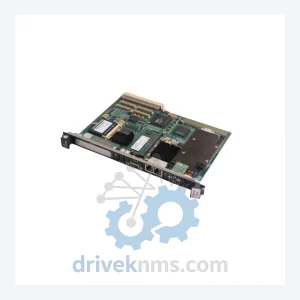
GE IC693 Series Modules IC693CBL328
GE Fanuc IC693CBL328 is listed for IC693 Series RFQ review. Confirm quantity, condition and destination before quotation.
RFQ-ready industrial model
Model: IC693DSM314
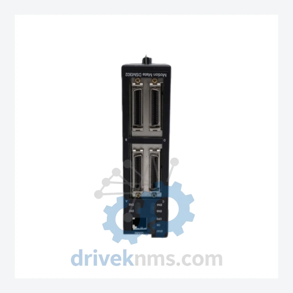
Product Overview
Commercial availability is handled through direct RFQ, model verification and export-oriented follow-up rather than public cart checkout.
Datasheet Preview
Use attached product manuals when available. If the manual is not public yet, request the full file directly through RFQ.
Commercial Path
Product pages on DRIVEKNMS are designed to verify model, brand and series first, then move the buyer into one clean quotation path.
Technical Dossier
The IC693 platform was introduced by GE Fanuc Automation in 1988 as a successor to the Series Six and Series Five PLC families. The original CPU module, the IC693CPU311, offered 6 KB of user memory and supported ladder diagram programming via the Logicmaster 90-30 software package running on DOS. By 1993, GE Fanuc released the IC693CPU341 with expanded floating-point math capability and peer-to-peer communications, targeting continuous process applications.
The mid-cycle refresh in 1997 introduced the IC693CPU351 and IC693CPU360, which added Ethernet TCP/IP capability natively and supported the Windows-based Proficy Machine Edition (PME) programming environment. These models also introduced the Genius Bus Controller integration, enabling the IC693 to serve as a head-end controller for distributed I/O networks across large plant footprints.
Compatibility note: IC693 modules are not electrically or mechanically interchangeable with IC695 (RX3i) modules. Baseplates, power supplies, and CPU modules are series-specific. Mixed-series configurations require the IC693CMM321 or IC695CMM004 communication bridge modules.
CPU Modules
Motion Control Modules
Discrete Input Modules
Discrete Output Modules
Analog I/O Modules
Communications Modules
Power Supply Modules
IC693 modules present specific test challenges due to their parallel backplane bus architecture and the age-related degradation patterns common in CMOS-based logic from the 1990s. DriveKNMS applies the following test protocol to all IC693 modules prior to shipment:
Continue The Model Path
Move from this exact model into the matching system hub, brand archive, model-family archive or lifecycle sourcing route before sending a final RFQ list.
Related Paths
GE Fanuc IC693CBL328 is listed for IC693 Series RFQ review. Confirm quantity, condition and destination before quotation.
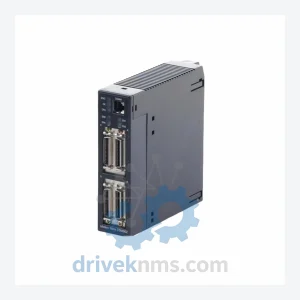
General Electric IC693DSM302 is listed for Series 90-30 RFQ review. Confirm quantity, condition and destination before quotation.
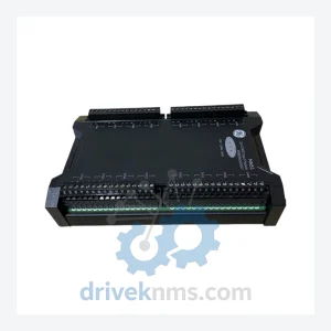
General Electric MDO11 369B1844G5002 is listed for Servo Drives RFQ review. Confirm quantity, condition and destination before quotation.