
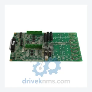
GE IS210AEAAH2BJE Module – IS210 Series
General Electric IS210AEAAH2BJE is listed for IS210 RFQ review. Confirm quantity, condition and destination before quotation.
RFQ-ready industrial model
Model: IS210AEBIH1BED
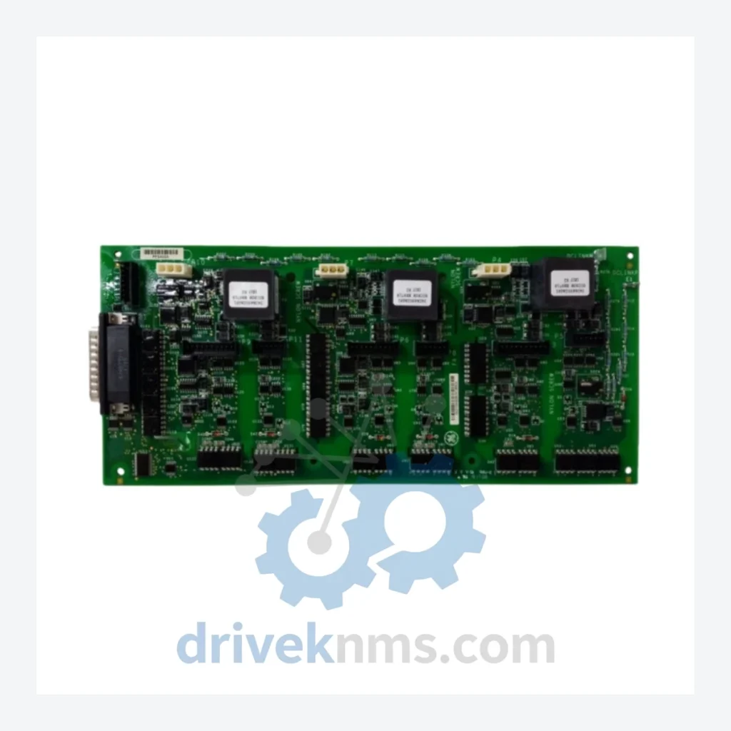
Product Overview
Commercial availability is handled through direct RFQ, model verification and export-oriented follow-up rather than public cart checkout.
Datasheet Preview
Use attached product manuals when available. If the manual is not public yet, request the full file directly through RFQ.
Commercial Path
Product pages on DRIVEKNMS are designed to verify model, brand and series first, then move the buyer into one clean quotation path.
Technical Dossier
The IS210 module family was introduced as part of the Mark VI Speedtronic turbine control system, which GE launched in the mid-1990s as a successor to the Mark V platform. The Mark VI architecture centralized turbine protection, sequencing, and I/O management into a VME-based rack system, with IS210-prefix modules serving as the standardized hardware layer.
Generation 1 (Mark VI, ~1995–2005): Initial IS210 modules used parallel backplane addressing and ARCNET for inter-module communication. Modules such as the IS210AEBIH1BED (AE Bridge Interface) and IS210BAIAH1A (Analog Input) defined the baseline I/O architecture. Compatibility was tightly coupled to specific Mark VI rack configurations (VCMI, VMIC, VMIO).
Generation 2 (Mark VI Enhanced / EX2100, ~2005–2015): GE extended the IS210 family to support the EX2100 excitation control system and Mark VI-e transitional hardware. IONet Ethernet-based communication was introduced alongside legacy ARCNET support. Modules in this era added dual-redundancy options and expanded diagnostic registers accessible via the ToolboxST configuration environment.
End-of-Life / Lifecycle Extension Phase (~2015–present): GE Vernova has formally migrated new installations to the Mark VIe platform (IS420-prefix modules). IS210-series hardware is no longer manufactured in volume. OEM spare parts availability is severely constrained. Plants operating Mark VI and EX2100 systems must source IS210 modules through authorized third-party suppliers with documented testing protocols to maintain turbine availability and avoid unplanned outages.
The following IS210-series modules are classified by functional category. Each entry represents a verified, commonly deployed part number within the Mark VI / EX2100 control architecture.
Bridge & Interface Modules
Digital I/O Modules
CPU & Controller Modules
Communication & Network Modules
Power Supply Modules
Speed & Vibration Modules
DriveKNMS maintains a dedicated inventory of IS210-series modules sourced from decommissioned Mark VI systems, controlled plant shutdowns, and verified surplus channels. All units are catalogued by part number, hardware revision, and firmware version. DriveKNMS provides:
IS210-series modules present specific testing challenges due to their VME backplane architecture, ARCNET bus dependency, and mixed analog/digital signal paths. DriveKNMS applies the following verification procedures to all IS210 units prior to dispatch:
Continue The Model Path
Move from this exact model into the matching system hub, brand archive, model-family archive or lifecycle sourcing route before sending a final RFQ list.
Related Paths
General Electric IS210AEAAH2BJE is listed for IS210 RFQ review. Confirm quantity, condition and destination before quotation.
General Electric IS200BPIBG1AEB is listed for Monitoring Systems RFQ review. Confirm quantity, condition and destination before quotation.
General Electric IS200RCSAG1ABB is listed for Monitoring Systems RFQ review. Confirm quantity, condition and destination before quotation.