

GE Fanuc IS200TBCIS2CCD I/O Terminal Board – Mark VI Redundant Control System
GE Fanuc IS200TBCIS2CCD is listed for Mark VI RFQ review. Confirm quantity, condition and destination before quotation.
RFQ-ready industrial model
Model: IS215UCCAM03A
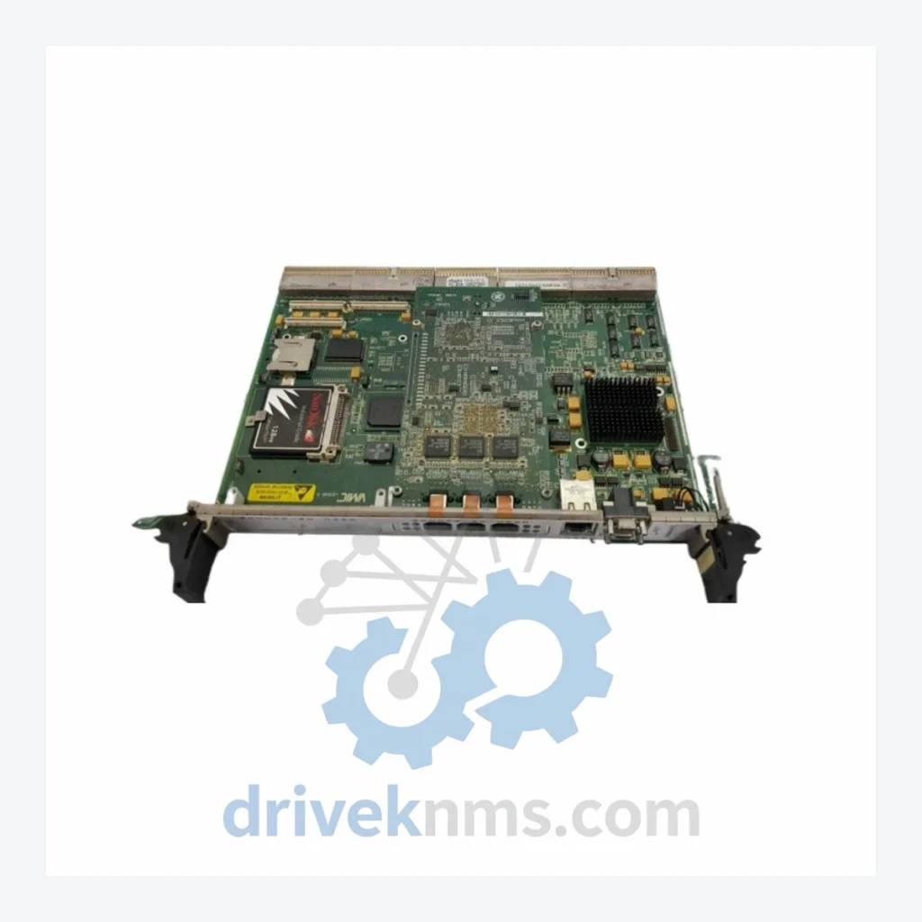
Product Overview
Commercial availability is handled through direct RFQ, model verification and export-oriented follow-up rather than public cart checkout.
Datasheet Preview
Use attached product manuals when available. If the manual is not public yet, request the full file directly through RFQ.
Commercial Path
Product pages on DRIVEKNMS are designed to verify model, brand and series first, then move the buyer into one clean quotation path.
Technical Dossier
The GE Mark VI Turbine Control System is one of the most widely deployed distributed control platforms in global heavy industry. Installed across combined-cycle power plants, nuclear auxiliary systems, petrochemical refineries, and offshore platforms, the Mark VI architecture represents GE's transition from relay-based and analog control into fully digital, redundant turbine management. The IS215UCCAM03A is a Unit Controller Card (UCC) within this ecosystem — the primary CPU-class module responsible for executing turbine control logic, managing I/O communication over the IONet backbone, and interfacing with the operator HMI via the Mark VI toolbox environment (ToolboxST). Facilities operating GE Frame 5, Frame 6, Frame 7, Frame 9, and LM-series gas turbines, as well as steam turbines and combined-cycle units, rely on Mark VI hardware for continuous, safety-critical operation. The installed base of Mark VI systems globally numbers in the tens of thousands of units, with many sites now operating hardware that is 15–25 years old — making reliable spare parts sourcing a primary operational concern for plant engineers and reliability teams.
GE's turbine control lineage progresses through several distinct generations. The Mark I / Mark II era (1960s–1970s) used relay logic and analog circuitry with no digital processing. Mark IV (early 1980s) introduced microprocessor-based control but remained largely proprietary and non-networked. Mark V (late 1980s–1990s) established the modular VME-bus architecture and introduced redundant I/O, becoming the dominant platform for Frame 6 and Frame 7 turbines through the 1990s. Mark VI (introduced ~1995, widely deployed through 2010s) replaced the VME bus with a proprietary high-speed serial network (IONet / ARCNET), introduced triple-redundant (TMR) control capability, and standardized on the IS2xx module family. Mark VIe (2005–present) is the current-generation successor, using Ethernet-based I/O (IONet over Ethernet), IEC 61131-3 structured programming, and a modernized ToolboxST environment. Mark VI and Mark VIe are not directly hardware-compatible, though ToolboxST supports both. Sites running Mark VI hardware face a defined obsolescence horizon: GE has progressively reduced active manufacturing support for IS2xx-series modules, making third-party refurbished and new-surplus inventory the primary supply channel for maintenance and emergency replacement.
The following represents a structured reference catalog of confirmed IS2xx-series Mark VI modules, organized by functional category. Each entry reflects a distinct hardware role within the Mark VI control architecture.
Controllers (CPU / Unit Controller Cards)
Digital Input (DI) Modules
Analog Input / Output (AI/AO) Modules
Communication & Network Modules
Power Supply Modules
Mark VI modules — particularly CPU-class cards such as the IS215UCCAM03A — incorporate complex multi-layer PCBs, FPGA-based logic, and proprietary ARCNET/IONet communication ASICs that require specialized test procedures beyond standard bench power-up verification. DriveKNMS applies the following test protocol to all Mark VI modules: Visual inspection covers component-level examination for capacitor ESR degradation, solder joint fatigue, and corrosion on backplane edge connectors. Powered functional test uses a dedicated Mark VI rack test fixture to verify module initialization, IONet communication handshake, and firmware version reporting via ToolboxST. I/O channel verification applies calibrated signal sources and loads to each input/output channel to confirm within-specification accuracy. Burn-in cycling subjects each module to thermal cycling (0°C to 55°C) over a minimum 48-hour period to screen for latent component failures. Final documentation records test results, firmware revision, and physical condition in a traceable inspection report shipped with each unit.
Continue The Model Path
Move from this exact model into the matching system hub, brand archive, model-family archive or lifecycle sourcing route before sending a final RFQ list.
Related Paths
GE Fanuc IS200TBCIS2CCD is listed for Mark VI RFQ review. Confirm quantity, condition and destination before quotation.
General Electric IS420ESWBH3A is listed for Mark VI RFQ review. Confirm quantity, condition and destination before quotation.
General Electric IS210BPPCH1AD is listed for Mark VI RFQ review. Confirm quantity, condition and destination before quotation.