GE UR Series Modules: UR6AV Digital I/O Module —
GE UR Series: Comprehensive Module Range and Technical Overview The GE Grid Solutions UR Series (Universal Relay) platform is one…
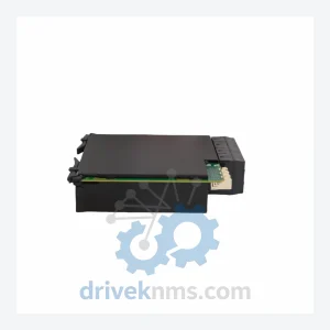
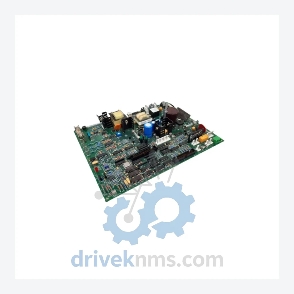
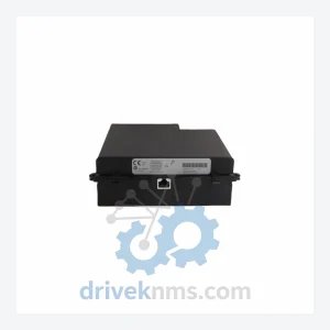
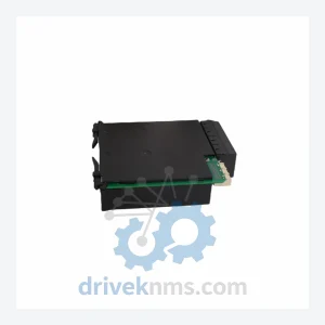
Model: UR9VM
Product Overview
Commercial availability is handled through direct RFQ, model verification and export-oriented follow-up rather than public cart checkout.
Datasheet Preview
Use attached product manuals when available. If the manual is not public yet, request the full file directly through RFQ.
Commercial Path
Product pages on DRIVEKNMS are designed to verify model, brand and series first, then move the buyer into one clean quotation path.
Technical Dossier
The GE UR (Universal Relay) Series, developed by GE Grid Solutions (formerly GE Multilin), is a platform-based digital protection and control relay system deployed across heavy industrial infrastructure worldwide. Installations span petrochemical complexes, nuclear power stations, oil refineries, offshore platforms, and high-voltage transmission substations. The UR platform is distinguished by its modular hardware architecture, which allows a single chassis to be configured for transformer protection, line protection, bus protection, motor protection, and generator protection by swapping or populating function-specific I/O and DSP modules. Its IEC 61850 GOOSE messaging capability and IEEE 1588 precision time synchronization make it a reference platform in modern digital substation deployments. The UR Series has accumulated millions of relay-years of field service, making it one of the most widely maintained protection platforms in the global installed base.
The UR platform was introduced in the late 1990s as GE Multilin's response to the industry shift from electromechanical and solid-state relays toward fully numerical, communicating protection devices. The first-generation UR chassis used a passive backplane with a CPU module, power supply module, and a series of interchangeable I/O modules occupying up to 12 slots. Communication was initially limited to RS-485 Modbus and DNP3. The second-generation UR introduced dual-redundant Ethernet ports, expanded GOOSE messaging under IEC 61850 Edition 1, and increased DSP processing capacity to handle more complex protection algorithms such as differential restraint with harmonic blocking. The third-generation UR (current production) supports IEC 61850 Edition 2, IEEE 1588v2 (PTP), IRIG-B time synchronization, and cybersecurity hardening per NERC CIP standards. Backward compatibility across generations is maintained at the chassis and wiring level for most module types, though firmware and configuration tool versions (EnerVista UR Setup) must be matched carefully. Modules from early-generation UR chassis are no longer manufactured but remain in active service at thousands of sites, creating sustained demand for tested surplus and refurbished units.
The following SKUs represent verified, commonly deployed modules within the GE UR platform. Each entry reflects a discrete hardware component with a defined functional role within the UR chassis architecture.
UR9VM: Universal relay chassis rear terminal module, voltage metering variant, provides analog voltage input termination for UR platform protection functions.
UR6AH: 6-slot UR chassis with AC/DC power supply, horizontal mounting, standard backplane for mid-size protection applications.
UR8AH: 8-slot UR chassis, AC/DC power supply, horizontal mount, expanded I/O capacity for complex protection schemes.
UR0AH: 19-inch rack-mount UR chassis, AC input power supply, horizontal orientation, full-width deployment.
URTDM: RTD (Resistance Temperature Detector) input module, supports 8-channel PT100/PT1000 thermal monitoring for motor and transformer protection.
URCM: Contact input/output module, 16 optically isolated digital inputs and 8 output relays, used for control logic and trip/close circuits.
URFM: FlexLogic programmable output module, provides configurable relay outputs for custom protection logic schemes.
URCAM: Current and voltage analog input module, 4 CT inputs and 4 VT inputs, core metering and protection sensing module.
URPC: Processor/CPU module for UR platform, runs protection algorithms, manages inter-module communication over internal backplane bus.
URPSL: Power supply module, low-range DC input (24–48 VDC), used in substation DC battery-backed panel applications.
URPSH: Power supply module, high-range DC input (125–250 VDC), standard substation battery bus compatibility.
URPSAC: Power supply module, AC input (100–240 VAC), for industrial panel installations without DC battery systems.
URCM16: 16-channel contact input module, high-density digital input for large switchgear control applications.
URTXM: Fiber-optic transceiver module for UR inter-relay communication, supports direct fiber GOOSE and peer-to-peer protection schemes.
URIOM: Analog I/O module, 4–20 mA output channels, used for metering output to SCADA analog input cards.
URSCM: Serial communication module, RS-232/RS-485, supports Modbus RTU and DNP3 serial protocols for legacy SCADA integration.
URECM: Ethernet communication module, dual RJ-45 or fiber SFP ports, IEC 61850 GOOSE and MMS, DNP3 over TCP/IP.
URGPS: GPS time synchronization module, IRIG-B output, provides microsecond-accurate time stamping for sequence-of-events recording.
UR Series modules present specific test challenges due to their backplane-dependent communication architecture and DSP-based protection logic. DriveKNMS applies a structured test protocol for all UR hardware: (1) Visual inspection for capacitor aging, PCB corrosion, and connector wear on the 96-pin backplane edge connector. (2) Power-on functional test using a UR chassis test bench with known-good CPU and power supply modules. (3) Backplane bus communication verification — each module must enumerate correctly on the internal UR communication bus and respond to the CPU's module identification query. (4) For I/O modules: all digital input channels are exercised with 24 VDC and 125 VDC test signals; all output relay contacts are tested for continuity and coil resistance. (5) For CPU modules: firmware version is read and recorded; EnerVista UR Setup connectivity is confirmed; protection element enable/disable functions are verified. (6) For communication modules: Ethernet port link negotiation, GOOSE subscription/publication, and Modbus register map access are tested. Modules that pass all stages are tagged with a DriveKNMS test certificate and serial number log.
Related Paths
GE UR Series: Comprehensive Module Range and Technical Overview The GE Grid Solutions UR Series (Universal Relay) platform is one…
GE UR Series: Comprehensive Module Range and Technical Overview The GE UR Series (Universal Relay) platform, developed by GE Grid…
GE UR8LV CT/VT Module – Obsolete UR Series Spare Part When a CT/VT input module fails inside a GE UR…