
Honeywell XDL505 I/O Module FSC Series
Honeywell XDL505 is listed for Monitoring Systems RFQ review. Confirm quantity, condition and destination before quotation.
RFQ-ready industrial model
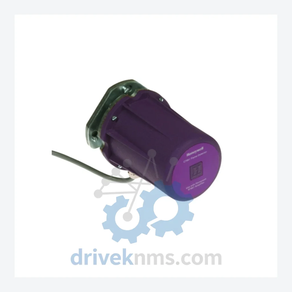
Model: C7061A1020
Product Overview
Commercial availability is handled through direct RFQ, model verification and export-oriented follow-up rather than public cart checkout.
Datasheet Preview
Use attached product manuals when available. If the manual is not public yet, request the full file directly through RFQ.
Commercial Path
Product pages on DRIVEKNMS are designed to verify model, brand and series first, then move the buyer into one clean quotation path.
Technical Dossier
RFQ support for obsolete parts: Send the model number, required quantity and destination so DriveKNMS can confirm sourcing options before quotation.
| Parameter | Value |
|---|---|
| Part Number | C7061A1020 |
| Manufacturer | Honeywell |
| Product Type | UV Flame Detector (Ultraviolet) |
| Supply Voltage | 120 / 230 V AC |
| Shutter Type | Shutter-equipped (self-checking) |
| Detection Method | Ultraviolet (UV) radiation sensing |
| Typical Application | Gas, oil, and combination burner flame supervision |
| Compatible Controls | Honeywell R4140, R7140, R7247, R7284, R7886 series burner controls |
| Discontinuation Status | Officially discontinued by Honeywell; no longer in production |
| Country of Origin | United States |
The C7061A1020 was designed for integration with Honeywell's R4140 and R7140 series burner management controls — systems that remain operational in refineries, chemical plants, power generation facilities, and industrial boiler rooms worldwide. These control architectures were engineered for 30+ year service lives, and many installations have no viable upgrade path without a complete combustion system redesign.
The self-checking shutter mechanism of the C7061A1020 is a safety-critical feature. It periodically interrupts the UV optical path to verify detector responsiveness, satisfying IEC 61511 and NFPA 85 functional safety requirements for burner management. Modern replacement detectors from current product lines are not dimensionally or electrically interchangeable with the R7140 control socket — meaning a substitute part does not exist without engineering rework.
For plant managers facing system retirement pressure: the cost of maintaining a C7061A1020-based flame detection system with verified spare parts is a fraction of the capital required to re-engineer the combustion control loop. A single unit in storage can defer a six-figure upgrade decision by three to five years. A strategic inventory of two to four units extends that window to a decade or beyond, provided the broader burner management hardware remains serviceable.
Facilities that have successfully extended C7061A1020-based system life by 5–10 years typically follow three practices: (1) maintain a minimum of two verified spare detectors on-site, (2) schedule annual functional testing of the shutter mechanism, and (3) document the firmware or relay logic version of the associated burner control to ensure replacement detectors are sourced to the correct revision. DriveKNMS can advise on revision compatibility prior to shipment.
Discontinued UV flame detectors sourced from secondary markets carry specific failure risks that differ from standard electronic components. Our 5-step QA protocol for the C7061A1020 addresses the failure modes most commonly observed in aged units:
Should I purchase more than one unit?
For any facility where the C7061A1020 is a single point of failure in a burner management system, holding a minimum of two spare units is the standard recommendation. Given that this part is no longer manufactured, current market availability is finite. Procurement decisions made today directly determine whether a replacement will be available at the next failure event — which cannot be scheduled.
Can DriveKNMS verify compatibility with my specific burner control revision?
Yes. Provide your burner control model and revision number prior to ordering. We will cross-reference against known compatibility data before confirming the order.
Continue The Model Path
Move from this exact model into the matching system hub, brand archive, model-family archive or lifecycle sourcing route before sending a final RFQ list.
Related Paths
Honeywell XDL505 is listed for Monitoring Systems RFQ review. Confirm quantity, condition and destination before quotation.
Honeywell U2-1018S-PF is listed for Monitoring Systems RFQ review. Confirm quantity, condition and destination before quotation.
Honeywell MC-GHAO11 51309540-175 is listed for Monitoring Systems RFQ review. Confirm quantity, condition and destination before quotation.