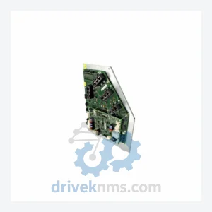
Kawasaki 50607-1273 / 50999-1950R00 Power Supply Modules - 50607-1273 50607-1273 50999-1950R00

Model: 50607-1273 50607-1273 50999-1950R00

Brand Kawasaki
Model 50607-1273 50607-1273 50999-1950R00
RFQ-ready model route Obsolete and surplus sourcing Export follow-up by model list

Product Overview

Commercial availability is handled through direct RFQ, model verification and export-oriented follow-up rather than public cart checkout.

Datasheet Preview

Datasheet Preview

Use attached product manuals when available. If the manual is not public yet, request the full file directly through RFQ.

Request Full Manual

Commercial Path

Use This Page To Confirm The Model, Then Move To RFQ

Product pages on DRIVEKNMS are designed to verify model, brand and series first, then move the buyer into one clean quotation path.

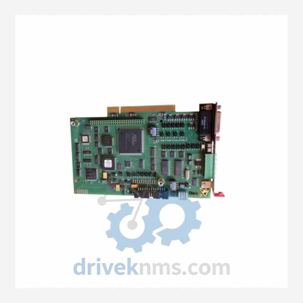
Technical Dossier

Product Details And Specifications

Kawasaki 50607 / 50999 Series Technical Notes

Kawasaki 50607 / 50999 Full Catalog & Functionalities (SKU List)

The following SKUs represent the documented range of Kawasaki robot controller power supply and associated control modules compatible with D-series and E-series controller platforms. Each entry reflects a verified part number within the Kawasaki spare parts ecosystem:

50607-1273: Primary DC power supply board for Kawasaki D-series robot controller cabinets.
50999-1950R00: Revised power supply PCB assembly; updated component revision of the 50607-1273 for E-series compatibility.
50607-1060: Servo amplifier power regulation module; controls DC bus for axis drive circuits.
50607-1061: Auxiliary power supply board; provides logic-level voltage rails to CPU and I/O backplane.
50607-1062: Regenerative discharge control board; manages braking resistor activation during deceleration.
50607-1100: Main controller CPU board for D-series; interfaces with teach pendant and motion planner.
50607-1101: Secondary CPU board; handles real-time interpolation and axis coordination.
50607-1200: Digital I/O interface board; 32-channel DI/DO for external PLC handshaking.
50607-1201: Analog I/O expansion board; 8-channel AI/AO for process feedback integration.
50607-1250: Serial communication adapter board; RS-232/RS-422 interface for host system connectivity.
50607-1300: Encoder feedback processing board; decodes resolver and incremental encoder signals from servo motors.
50607-1350: Safety relay and emergency stop monitoring board; dual-channel safety circuit compliance.
50999-1800R00: Backplane bus interface board; manages data routing between CPU and I/O modules in E-series chassis.
50999-1900R00: Motion control DSP board; dedicated signal processor for trajectory calculation in high-speed applications.
50999-2000R00: Fieldbus communication module; supports DeviceNet and PROFIBUS-DP protocol integration.
50999-2100R00: Teach pendant interface board; manages pendant display, keypad, and enable switch circuits.
50999-2200R00: Axis expansion board; enables 7th and 8th axis control for extended-reach robot configurations.

Quality Control for the Kawasaki 50607 / 50999 Range

Power supply boards in the 50607 and 50999 series present specific failure modes that require targeted test procedures. Common failure signatures include capacitor ESR degradation on the primary filter stage, MOSFET gate driver failure causing intermittent DC bus undervoltage faults, and PCB trace corrosion on units exposed to high-humidity environments. DriveKNMS applies the following test protocol to all 50607-1273 and 50999-1950R00 units: (1) Visual inspection under 10x magnification for PCB delamination, solder joint cracking, and component physical damage. (2) ESR measurement on all electrolytic capacitors above 100µF. (3) Static load test at rated output voltage (typically 24VDC and 5VDC rails) with calibrated resistive load bank. (4) Dynamic load transient test simulating servo amplifier inrush current at axis enable. (5) Thermal imaging under full load to identify hot spots indicating marginal components. (6) Functional validation in a Kawasaki D-series or E-series controller test bench with live axis enable and fault reset cycle. Units passing all six stages are issued a DriveKNMS test certificate included with shipment documentation.

Continue The Model Path

Use system, brand and series routes to compare related published models.

Move from this exact model into the matching system hub, brand archive, model-family archive or lifecycle sourcing route before sending a final RFQ list.

WhatsApp Prefilled Inquiry Email sale@driveknms.com Phone +86 18359293191 Top Back To Top