
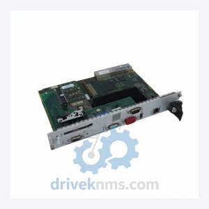
Kontron CP6500-V Controller Board – Obsolete CompactPCI Spare Part
Kontron CP6500-V is listed for PLC Modules RFQ review. Confirm quantity, condition and destination before quotation.
RFQ-ready industrial model
Model: ASMC2177G
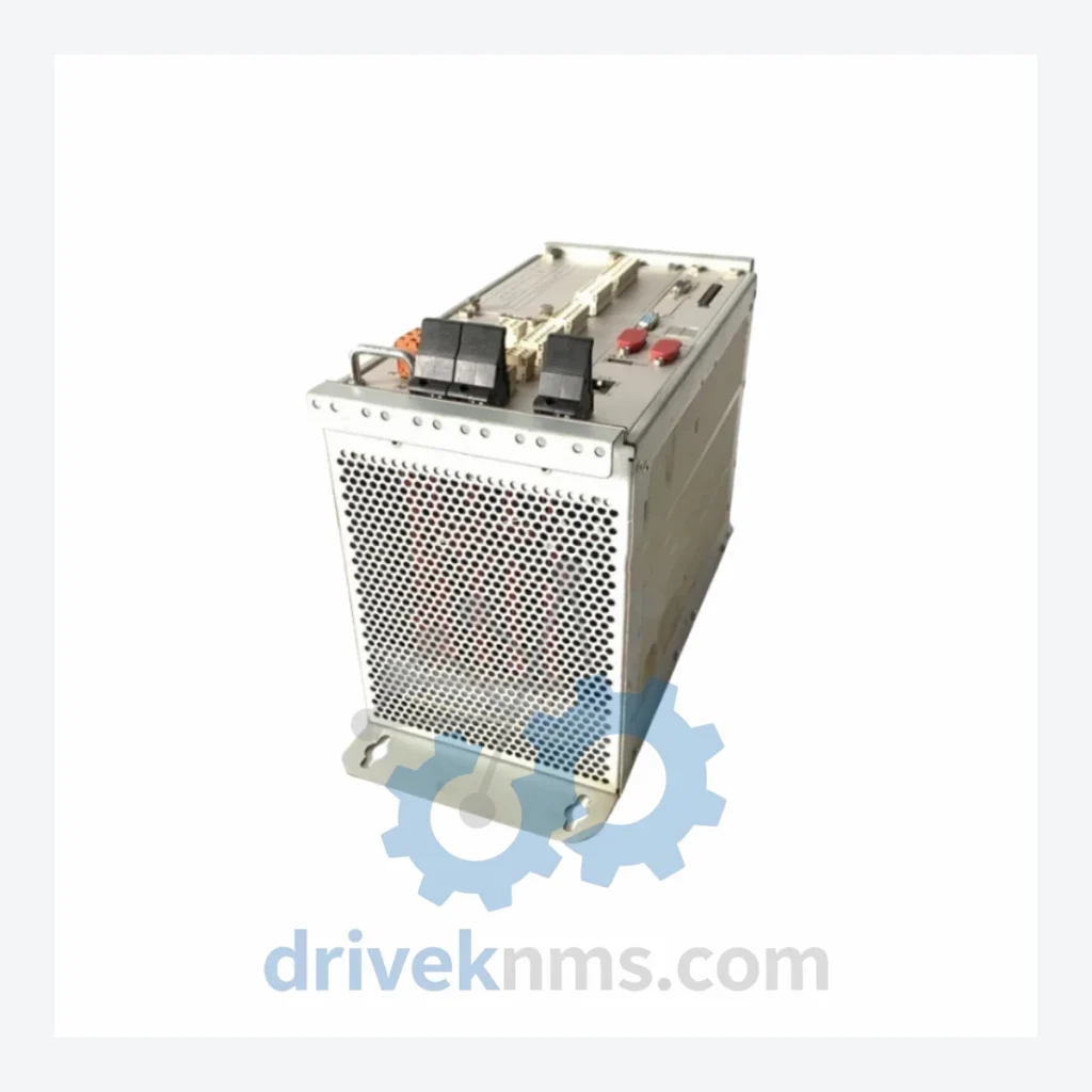
Product Overview
Commercial availability is handled through direct RFQ, model verification and export-oriented follow-up rather than public cart checkout.
Datasheet Preview
Use attached product manuals when available. If the manual is not public yet, request the full file directly through RFQ.
Commercial Path
Product pages on DRIVEKNMS are designed to verify model, brand and series first, then move the buyer into one clean quotation path.
Technical Dossier
The ASMC architecture is built on Kontron's CompactPCI and PICMG-compliant backplane standards, evolving through several generations of processor and bus technology. Early ASMC modules utilized Intel x86 single-board computer architectures with ISA/PCI bus interfaces, targeting VMEbus and CompactPCI chassis environments common in SCADA and DCS integration projects of the late 1990s and early 2000s. Mid-generation modules transitioned to Intel Core and Atom processor families, incorporating PCIe Gen 2 backplane connectivity, IPMI 2.0 baseboard management, and ECC DDR3 memory subsystems. Current and late-series ASMC modules support PCIe Gen 3, DDR4 ECC, and extended temperature ranges of -40°C to +85°C for harsh environment deployment. Compatibility across generations is chassis-dependent; PICMG 2.0 R3.0 compliance is maintained across most mid-to-late series units, but early-generation modules require verification against specific backplane pinout revisions. Firmware and BIOS versions are not cross-compatible between generations without factory re-flashing.
The following SKUs represent verified models within the Kontron ASMC series, classified by functional category:
Controller / SBC Modules
I/O Modules
Communication & Network Adapter Modules
Power Supply Modules
ASMC modules present specific test challenges due to their CompactPCI backplane bus architecture and multi-function I/O subsystems. DriveKNMS applies a structured test protocol to all ASMC units prior to shipment. Each controller module undergoes POST (Power-On Self-Test) verification, BIOS integrity check, and memory subsystem stress testing using industry-standard burn-in tools. Backplane connector integrity is inspected under magnification for pin deformation, oxidation, and solder joint fatigue — common failure modes in modules removed from high-vibration environments. I/O modules are tested under active signal conditions: digital I/O channels are verified for correct logic levels and isolation resistance; analog modules are calibrated against traceable reference standards. Communication modules are validated for link establishment, packet integrity, and protocol compliance using dedicated bus analyzers. All units are powered in a controlled environment for a minimum 24-hour burn-in period before final inspection and packaging.
Continue The Model Path
Move from this exact model into the matching system hub, brand archive, model-family archive or lifecycle sourcing route before sending a final RFQ list.
Related Paths
Kontron CP6500-V is listed for PLC Modules RFQ review. Confirm quantity, condition and destination before quotation.
Kontron CP6000/FTC-02 is listed for Fault-Tolerant Series RFQ review. Confirm quantity, condition and destination before quotation.
Kontron VMEM-S2 is listed for Servo Drives RFQ review. Confirm quantity, condition and destination before quotation.