Technical Dossier
Product Details And Specifications
KUKA KR C4 Series Technical Notes
The Evolution of KR C4 Architecture
The KR C4 platform underwent several hardware revisions between 2009 and 2022. Early production units (2009–2013) used a discrete power supply topology with separate rectifier, DC bus, and logic supply boards. Mid-generation revisions (2014–2018) consolidated some power functions and introduced improved EMC filtering. Late-production units (2019–2022) shifted toward integrated drive-power modules with revised firmware dependencies.
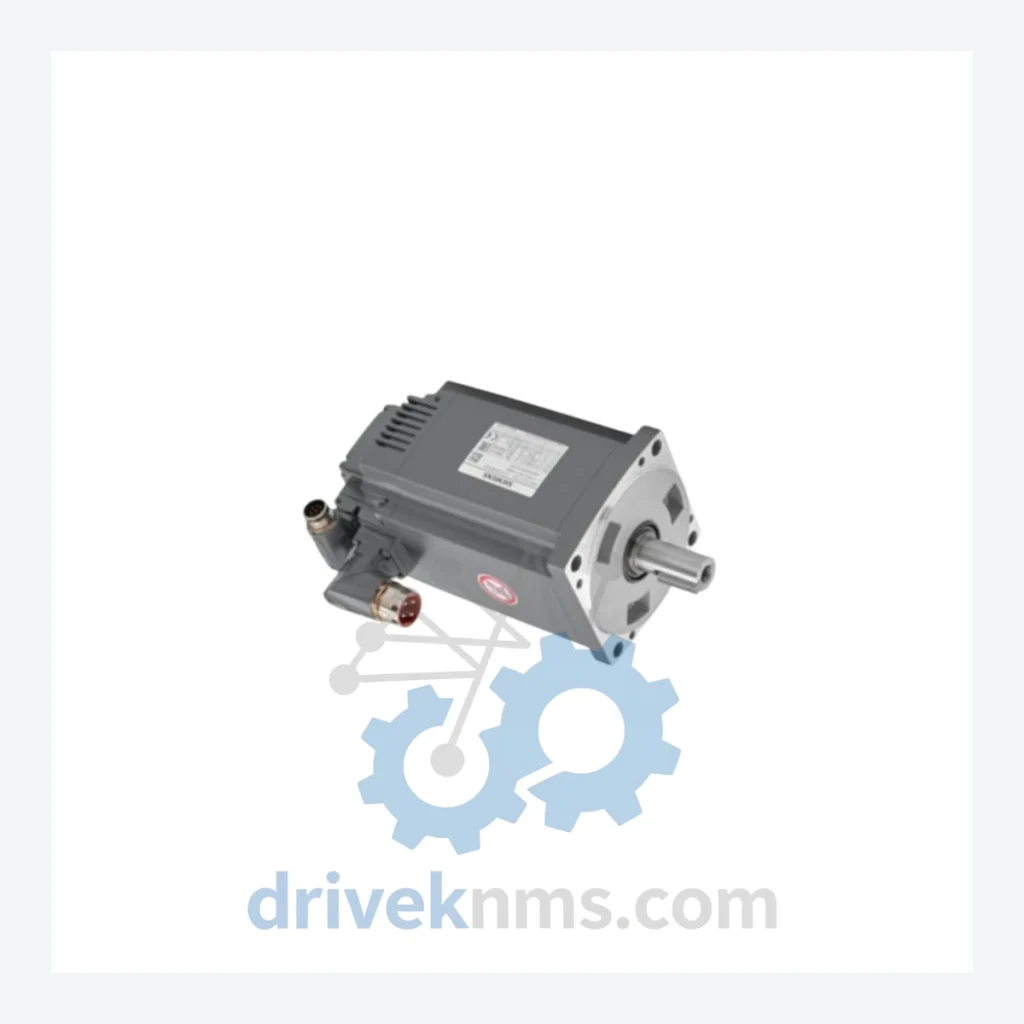
This generational fragmentation creates a direct compatibility challenge for maintenance engineers: a replacement module sourced from a different production batch may require firmware alignment or bus address reconfiguration. The 1FK7103-5AF81-1YY3-Z servo motor (Siemens SIMOTICS S-1FK7 series, 6.9 kW, 400V, flange-mount) is the axis drive motor paired with this controller assembly. Its drive parameters are stored in the KR C4's KPS (KUKA Power Supply) module — meaning motor and controller components must be treated as a matched set during replacement planning.
KR C4 Full Catalog & Functionalities (SKU List)
The following SKUs represent verified components within the KUKA KR C4 ecosystem. Each entry reflects a distinct functional role within the controller or drive chain:
00-131-492: KR C4 internal power supply assembly, 27V DC logic rail, primary axis
C400-216-801: KR C4 power electronics module, DC bus interface, regenerative capable
00-169-213: KR C4 27V DC auxiliary power board, logic and I/O supply
1FK7103-5AF81-1YY3-Z: Siemens SIMOTICS S servo motor, 6.9 kW, 400V, matched axis drive
00-117-340: KR C4 KPS600 power supply unit, 600V DC bus, standard cabinet
00-117-341: KR C4 KPS600 power supply unit, variant with extended thermal rating
00-130-468: KR C4 RDC (Resolver Digital Converter) board, axis feedback processing
00-130-469: KR C4 RDC board, extended axis count variant (7-axis configuration)
00-168-894: KR C4 EtherCAT master communication card, internal bus controller
00-168-895: KR C4 EtherCAT slave interface module, I/O expansion
00-160-552: KR C4 safety controller board (KSB), SIL2/PLe certified
00-160-553: KR C4 safety interface module, external safety circuit integration
00-118-935: KR C4 main computer board (PC mainboard), Intel-based, KUKA.VxWorks host
00-118-936: KR C4 compact main computer board, KR C4 compact cabinet variant
00-132-017: KR C4 KPP (KUKA Power Pack) servo drive module, axes 1–3
00-132-018: KR C4 KPP servo drive module, axes 4–6, wrist axis group
00-156-872: KR C4 cabinet fan assembly, forced-air cooling, standard cabinet
00-156-873: KR C4 heat exchanger unit, sealed cabinet thermal management
00-109-435: KUKA smartPAD teach pendant, KR C4 compatible, 7m cable
00-109-436: KUKA smartPAD cable assembly, 10m extension, KR C4 interface
Sourcing Hard-to-Find & Obsolete KR C4 Parts
For facilities managing a fleet of KR C4 robots, DriveKNMS recommends a structured spare parts buffer strategy: maintain a minimum of one KPS module, one RDC board, and one KPP drive module per 10 operational robots. This buffer, sourced at current market prices, represents a fraction of the cost of a single unplanned production stoppage in an automotive or process industry environment.
Quality Control for the KR C4 Range
KR C4 power and drive modules present specific failure modes that require targeted inspection protocols. DriveKNMS applies the following five-stage process to all KR C4 components prior to dispatch:
Stage 1 – Electrolytic Capacitor Assessment: DC bus capacitors and logic supply filter capacitors are measured for capacitance retention and ESR (Equivalent Series Resistance). Units with capacitance below 85% of rated value or ESR above threshold are recapped using equivalent-specification components.
Stage 2 – Firmware Version Verification: Where accessible, onboard firmware versions are read and documented. KR C4 modules with known firmware incompatibilities (particularly RDC and safety boards) are flagged and matched to compatible controller generations.
Stage 3 – Pin and Connector Inspection: All backplane connectors, Harting interfaces, and signal pins are inspected under magnification for oxidation, fretting corrosion, and mechanical deformation. Affected contacts are treated or the connector assembly is replaced.
Stage 4 – Functional Load Test: Power supply modules are tested under resistive load at rated output current. Drive modules are bench-tested for gate drive signal integrity and DC bus regulation.
Stage 5 – EtherCAT Bus Communication Test: Communication modules are verified for correct EtherCAT frame handling and node address response using a KR C4-compatible test harness.