
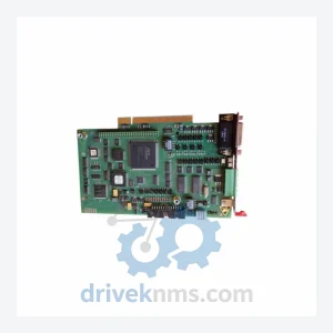
KUKA KRC Safety Board Modules: 00-138-379
Kuka 00-138-379 is listed for Controller Cards RFQ review. Confirm quantity, condition and destination before quotation.
RFQ-ready industrial model
Model: KPC400-284-170
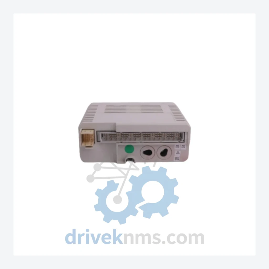
Product Overview
Commercial availability is handled through direct RFQ, model verification and export-oriented follow-up rather than public cart checkout.
Datasheet Preview
Use attached product manuals when available. If the manual is not public yet, request the full file directly through RFQ.
Commercial Path
Product pages on DRIVEKNMS are designed to verify model, brand and series first, then move the buyer into one clean quotation path.
Technical Dossier
The KUKA KPC400 series represents a core control platform deployed across heavy industrial environments globally, including chemical processing plants, nuclear facilities, and petroleum refineries. As the primary controller architecture for KUKA robot systems in the KR C2 and KR C3 controller generations, the KPC400 series boards govern motion control, I/O processing, safety logic, and fieldbus communication. Installed base figures span multiple decades of continuous operation, making lifecycle support and spare parts availability a critical operational concern for plant maintenance teams worldwide.
The KPC400 platform was introduced as part of KUKA's transition from relay-based robot controllers to fully digital, PC-based control architectures in the mid-1990s. Early KPC400 variants operated within the KR C1 ecosystem, utilizing ISA-bus backplane communication and proprietary KUKA DSE (Drive System Electronics) interfaces. As the KR C2 controller became the industry standard through the 2000s, the KPC400 board family was revised to support PCI-bus architecture, expanded memory addressing, and enhanced real-time OS compatibility (VxWorks and Windows XP Embedded).
By the KR C3 and early KR C4 transition period, the KPC400 series entered its mature/end-of-life phase. KUKA officially discontinued active production of most KPC400 variants, with the KR C4 platform (based on the KPC4 and KPC5 board families) serving as the designated successor. Facilities operating legacy KR C2 and KR C3 systems must now rely on aftermarket suppliers and certified refurbishers for board-level replacements. Compatibility between KPC400 sub-variants is version-specific; firmware revisions, BIOS versions, and DSE interface pinouts must be verified before substitution.
The following SKUs represent verified, commonly sourced components within the KUKA KPC400 control board family. Each entry reflects a distinct hardware revision or functional variant:
KPC400-284-170: Main CPU control board for KR C2 controller; primary motion and I/O coordination.
KPC400-284-160: Earlier CPU revision; compatible with KR C2 ed05 and prior firmware stacks.
KPC400-284-180: Revised memory configuration; supports extended axis count configurations.
KPC400-284-200: Late-production KR C2 CPU board; enhanced thermal management design.
KPC400-284-100: Base-revision control board; used in early KR C2 deployments pre-2002.
KPC400-284-120: Intermediate revision with updated BIOS; improved DSE handshake stability.
KPC400-284-140: Mid-series CPU board; common in KR 6, KR 16, and KR 30 robot pairings.
KPC400-284-210: Final production revision; highest firmware compatibility ceiling in the KPC400 line.
KPC400-284-190: Variant with modified PCI slot allocation; used in multi-axis external axis configurations.
KPC400-284-130: Transitional revision bridging ISA-to-PCI backplane architecture changes.
KPC400-284-150: Standard production board; widest installed base across KR C2 global fleet.
KPC400-284-110: Early PCI-bus variant; requires specific KSS (KUKA System Software) version 4.x.
KPC400-284-220: Extended-temperature variant; specified for foundry and high-ambient environments.
KPC400-284-230: Communication-enhanced revision; supports PROFIBUS DP master integration.
KPC400-284-240: Final catalog entry; includes onboard DeviceNet interface option for legacy cell integration.
The KPC400 control board presents specific test challenges due to its integrated backplane bus interface, onboard DSE communication logic, and multi-layer PCB construction. DriveKNMS applies a structured test protocol to each unit prior to dispatch:
Visual and physical inspection: Component-level examination for capacitor degradation, solder joint fatigue, and connector pin integrity across all edge connectors and PCI slots. Power rail verification: Bench-level power supply simulation confirming stable 3.3V, 5V, and 12V rail behavior under load. BIOS and firmware interrogation: Each board is booted in a controlled KR C2 test rig to confirm BIOS version, POST completion, and KSS software handshake. DSE communication test: Functional validation of the Drive System Electronics interface using KUKA-compatible DSE simulation hardware to confirm axis communication integrity. Thermal cycling: Boards are subjected to operational temperature cycling to identify latent thermal failures common in aged PCB assemblies. Final functional run: Full motion control simulation confirming interrupt handling, I/O polling, and real-time task scheduling performance within KSS specification tolerances.
Continue The Model Path
Move from this exact model into the matching system hub, brand archive, model-family archive or lifecycle sourcing route before sending a final RFQ list.
Related Paths
Kuka 00-138-379 is listed for Controller Cards RFQ review. Confirm quantity, condition and destination before quotation.
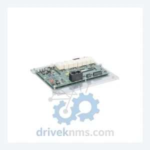
Kuka 00-161-116 is listed for KRC Series RFQ review. Confirm quantity, condition and destination before quotation.
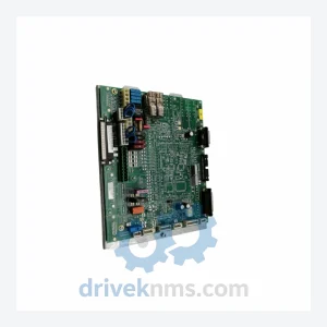
Kuka 00-127-754 is listed for Controller Cards RFQ review. Confirm quantity, condition and destination before quotation.