
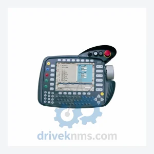
KUKA KCP2 Teach Pendant Modules
KUKA KCP2 Series: Comprehensive Module Range and Technical Overview The KUKA KCP2 (KUKA Control Panel 2) teach pendant is the…
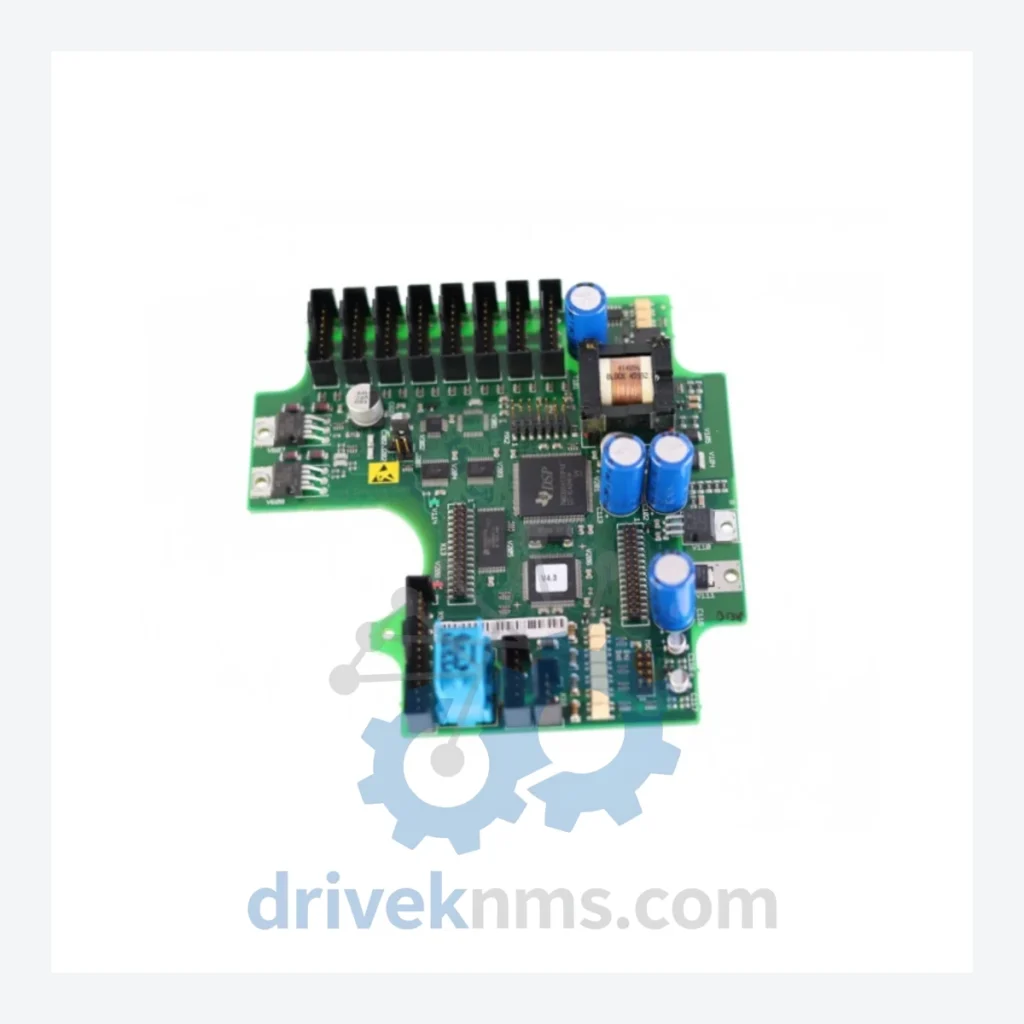
Model: KRC4 00-168-334 00-181-563 KRC2 00-126-383 KRC2RDW 00-119-966
Product Overview
Commercial availability is handled through direct RFQ, model verification and export-oriented follow-up rather than public cart checkout.
Datasheet Preview
Use attached product manuals when available. If the manual is not public yet, request the full file directly through RFQ.
Commercial Path
Product pages on DRIVEKNMS are designed to verify model, brand and series first, then move the buyer into one clean quotation path.
Technical Dossier
The KUKA KRC (KUKA Robot Controller) series represents the backbone of KUKA industrial robot installations across global heavy industries — including automotive body-in-white lines, chemical plant material handling, nuclear facility maintenance robots, and refinery pipeline welding systems. With an installed base spanning several decades and hundreds of thousands of units worldwide, KRC-series controller boards remain among the most actively sourced spare parts in the industrial robotics aftermarket.
The KRC2 platform, introduced in the late 1990s, established KUKA's modular controller architecture. The KRC4, launched in 2011, unified safety, motion control, and field bus communication onto a single hardware ecosystem. Both generations remain in active production use globally, and their circuit board components — including the specific SKUs covered on this page — are subject to ongoing demand from maintenance engineers and procurement teams managing long-lifecycle robot fleets.
The KRC1 (mid-1990s) used a proprietary VME-bus architecture with discrete analog servo amplifiers. Component sourcing for KRC1 is now almost entirely dependent on the secondary market, as OEM support has been fully discontinued.
The KRC2 generation (1999–2010) introduced a PC-based open architecture running Windows XP Embedded, with a standardized backplane connecting the KPS (power supply), KSP (servo pack), and DSE (drive system electronics) boards. Key compatibility constraints: KRC2 boards are not interchangeable with KRC2 ed05 variants without firmware alignment. The 00-126-383 circuit board is a core logic card within the KRC2 ecosystem, managing internal bus arbitration and I/O signal routing.
The KRC2 RDW (Resolver-Digital Converter) board — part number 00-119-966 — handles encoder signal conversion for all six robot axes. Failure of this board typically manifests as axis position errors or E-Stop faults. It is one of the highest-turnover spare parts in the KRC2 platform due to its exposure to vibration and thermal cycling.
The KRC4 generation (2011–present) consolidated controller architecture onto a single cabinet with integrated safety PLC (KSB — KUKA Safety Board), EtherCAT-based internal communication, and Windows 7 Embedded. The 00-168-334 and 00-181-563 are KRC4 circuit board cards associated with power management and internal communication routing. Compatibility between KRC4 and KRC4 compact / KRC4 smallSize variants requires verification of hardware revision levels before substitution.
The KRC5 platform (2020–present) introduces further integration, but KRC4 remains the dominant installed base for the 2026 maintenance cycle, ensuring sustained demand for KRC4 spare boards through at least 2032 under standard 10-year support windows.
The following SKUs represent the most commonly sourced circuit board and electronic module parts across the KRC2 and KRC4 controller families. All models listed are verified components within the KUKA KRC ecosystem.
KRC4 Platform — Circuit Boards & Electronic Modules:
KRC2 Platform — Circuit Boards & Electronic Modules:
The KRC2 platform entered end-of-life support from KUKA AG in 2019. OEM spare part availability through authorized channels is now severely constrained, with lead times from official distributors frequently exceeding 16–24 weeks for circuit board components — when available at all.
DriveKNMS maintains a dedicated inventory of KRC2 and KRC4 circuit board cards sourced through verified industrial surplus channels, decommissioned robot fleet buybacks, and authorized secondary market partners. Our procurement network spans Europe, North America, and Asia-Pacific, enabling access to components that are no longer listed in active OEM catalogs.
For procurement managers operating under planned maintenance schedules or responding to unplanned downtime, DriveKNMS provides: confirmed stock status before invoice, part number cross-reference verification, hardware revision compatibility checks, and export documentation compliant with international trade regulations. All transactions are supported by multi-currency payment options (USD, EUR, CNY, HKD) and standard commercial invoice / packing list documentation for customs clearance.
Delivery is executed via DHL Express or FedEx International Priority, with typical transit times of 3–7 business days to major industrial hubs globally. Emergency same-day dispatch is available for in-stock items upon order confirmation before 14:00 CST.
KUKA KRC circuit boards present specific testing challenges due to their integration of high-voltage DC bus interfaces, real-time EtherCAT communication stacks, and safety-rated I/O channels. Standard bench testing is insufficient for validating functional integrity.
DriveKNMS applies a structured test protocol for all KRC series boards prior to dispatch:
Each dispatched unit is accompanied by a test report, serial number record, and 12-month warranty covering manufacturing defects and functional failure under normal operating conditions. Warranty claims are processed within 5 business days of receipt of the returned unit.
For RFQ submissions, part number verification, or bulk procurement inquiries:
© 2026 DriveKNMS. All trademarks belong to their respective owners. Specifications are for reference only and subject to change without notice. Verify all parameters against official documentation before installation.
Related Paths
KUKA KCP2 Series: Comprehensive Module Range and Technical Overview The KUKA KCP2 (KUKA Control Panel 2) teach pendant is the…
KUKA KCP2 VKCP2 Robot Control Panel: Sourcing Strategy & Asset Return Value in a Constrained Global Supply Chain The KUKA…
KUKA KVGA Series: Comprehensive Module Range and Technical Overview The KUKA KVGA (KRC Video Graphics Adapter) series is a family…