
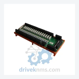
Robicon A5E01649374 Control Module – Obsolete Perfect Harmony Series Spare Part
Robicon A5E01649374 is listed for Harmony RFQ review. Confirm quantity, condition and destination before quotation.
RFQ-ready industrial model
Model: A1A283739.00
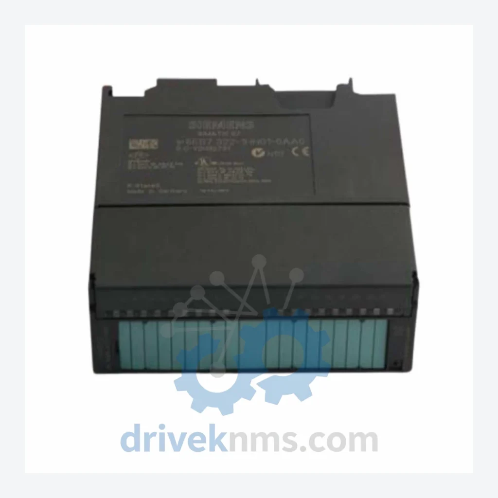
Product Overview
Commercial availability is handled through direct RFQ, model verification and export-oriented follow-up rather than public cart checkout.
Datasheet Preview
Use attached product manuals when available. If the manual is not public yet, request the full file directly through RFQ.
Commercial Path
Product pages on DRIVEKNMS are designed to verify model, brand and series first, then move the buyer into one clean quotation path.
Technical Dossier
The modular architecture of Perfect Harmony means that individual power cells, control boards, fiber optic communication modules, and I/O assemblies can be replaced independently without full drive replacement. This design philosophy has extended the operational lifespan of many installations well beyond 20 years, creating sustained global demand for original and equivalent spare parts — including the A1A283739.00 control module covered on this page.
The Perfect Harmony platform has undergone several distinct architectural generations since its introduction in the early 1990s:
Generation 1 (1992–1998): Original Robicon-designed analog/digital hybrid control boards. Proprietary backplane communication. Limited diagnostics. Many of these units remain in service in legacy chemical and mining installations. Spare parts availability is critically low.
Generation 2 (1998–2006): Transition to fully digital DSP-based control. Introduction of the modular power cell concept with standardized fiber optic links between the master controller and individual H-bridge cells. The A1A-prefix board numbering convention was established during this period. A1A283739.00 belongs to this generation's control and interface board family.
Generation 3 (2006–2014): Siemens integration era. Rebranded as Siemens ROBICON Perfect Harmony. Enhanced HMI, Profibus/Profinet communication options, and improved cell bypass logic. Many Gen 2 boards remain cross-compatible at the backplane level.
Generation 4 / GH180 (2014–Present): Current production platform. Siemens GH180 series. Fully integrated into TIA Portal ecosystem. Not backward-compatible with Gen 1/2 control hardware at the board level, though power cell form factors are partially interchangeable.
For sites running Gen 1 and Gen 2 hardware, the supply of original control boards such as A1A283739.00 is the primary maintenance bottleneck. DriveKNMS specializes in sourcing and validating these legacy assemblies.
The following SKUs represent verified components within the ROBICON Perfect Harmony drive system ecosystem. Each entry reflects a distinct functional role within the drive architecture:
A1A283739.00: Master control interface board, Gen 2 backplane communication and I/O coordination
A1A283739.01: Revised revision of master control board with updated firmware EEPROM
A1A283740.00: Fiber optic transmitter/receiver board, cell-to-controller link
A1A283741.00: Gate driver board for H-bridge power cell, IGBT firing control
A1A283742.00: Cell bypass relay board, automatic fault isolation module
A1A283743.00: DC bus voltage sensing and feedback board
A1A283744.00: Phase current measurement board, hall-effect sensor interface
A1A283745.00: Analog I/O expansion board, 4–20 mA signal conditioning
A1A283746.00: Digital I/O interface board, 24 VDC discrete signal termination
A1A283747.00: Power supply board, +5 V / ±15 V / +24 V regulated outputs for control rack
A1A283748.00: Serial communication adapter, RS-485 / Modbus RTU interface
A1A283749.00: Encoder feedback board, speed reference input processing
A1A283750.00: Thermal management controller, fan speed regulation and overtemperature alarm
A1A283751.00: HMI interface board, operator panel keypad and display driver
A1A283752.00: Profibus DP communication module, fieldbus integration adapter
A1A283753.00: Redundant power cell monitoring board, parallel cell status aggregation
A1A283754.00: Ground fault detection board, insulation resistance monitoring
The ROBICON Perfect Harmony Gen 1 and Gen 2 control board families have been out of OEM production for over a decade. Siemens no longer manufactures or stocks the majority of A1A-series boards as independent spare parts. End users operating these drives face three options: full drive replacement (capital-intensive, requires process shutdown), reverse-engineered third-party boards (variable quality, compatibility risk), or sourcing verified original assemblies from specialist distributors.
DriveKNMS supports installed-base sourcing for this series through RFQ review, including model matching, condition checks and documentation requirements before quotation.
Perfect Harmony control boards present specific test challenges due to their dependence on backplane communication protocols and fiber optic signal integrity. Standard bench power-up testing is insufficient to validate functional status. DriveKNMS applies the following test protocol to all Perfect Harmony boards:
Visual Inspection: Component-level examination for capacitor bulge, PCB delamination, solder joint fatigue, and connector pin corrosion. Boards with any evidence of arc damage or thermal stress are rejected at this stage.
Powered Static Test: Board is energized on a dedicated test jig replicating the Perfect Harmony backplane voltage rails. All regulated supply outputs are measured and verified against OEM specification tolerances.
Functional Communication Test: For boards with fiber optic interfaces (including the A1A283739.00 family), optical transmit power and receive sensitivity are measured. Communication handshake with a reference controller board is verified.
Burn-In Cycle: Boards are subjected to a minimum 24-hour thermal cycling burn-in at operating temperature to screen for latent component failures.
Continue The Model Path
Move from this exact model into the matching system hub, brand archive, model-family archive or lifecycle sourcing route before sending a final RFQ list.
Related Paths
Robicon A5E01649374 is listed for Harmony RFQ review. Confirm quantity, condition and destination before quotation.
Robicon A1A460A68.23M/460A68.10 is listed for Harmony RFQ review. Confirm quantity, condition and destination before quotation.
Robicon A5E01708486 is listed for Harmony RFQ review. Confirm quantity, condition and destination before quotation.